Downhole while-drilling gas-logging testing device

A gas logging, logging and testing device technology, applied in wellbore/well components, earth-moving drilling, etc., can solve the problems of information lag, loss, and inability to reflect the relevant information of the downhole drill bit in real time, so as to solve the information lag and improve the accuracy sexual effect

Pending Publication Date: 2018-07-24
中石化石油工程技术服务有限公司 +2
View PDF0 Cites 5 Cited by
  • Summary
  • Abstract
  • Description
  • Claims
  • Application Information

AI Technical Summary

Problems solved by technology

However, the drilling fluid needs to go through a long annular pipeline (with different drilling depths, the length of the pipeline is different, generally as long as several kilometers) to return from the destination layer to the surface. Relevant information; at the same time, during the flow of drilling fluid back to the ground through the annular space, relevant environmental conditions such as temperature and pressure change dynamically with the flow of drilling fluid in the pipeline, and the dissolved gas in the drilling fluid may also flow During the conversion to free state, part of the gas will enter the degasser with the drilling fluid for degassing, but some gas may rise from the drilling fluid to the ground and escape directly into the air through the liquid surface, affecting subsequent gas detection data the accuracy of
[0003] In recent years, the requirements for drilling speed and efficiency have become higher and higher, and the requirements for gas analysis and safety have become more and more stringent. Traditional gas logging technology has been difficult to meet the needs of oil and gas exploration and development.

Method used


Image

  • Downhole while-drilling gas-logging testing device
  • Downhole while-drilling gas-logging testing device

Examples


Embodiment Construction

[0015] In order to make the above and other objects, features and advantages of the present invention more comprehensible, the preferred embodiments are listed below and shown in the accompanying drawings in detail as follows.

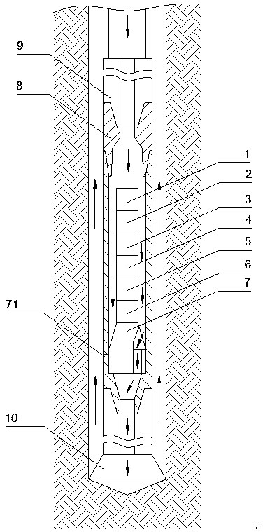
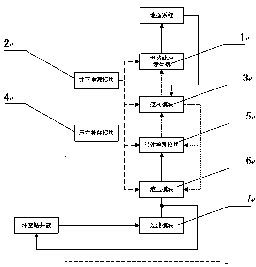
[0016] Such as figure 1 and figure 2 as shown, figure 1 It is the structural diagram of the downhole gas logging while drilling and mud logging testing device of the present invention, figure 2 It is the schematic diagram of the downhole gas logging while drilling testing device. The downhole gas logging while drilling test device includes a mud pulse generator 1 , a downhole power supply module 2 , a control module 3 , a pressure compensation module 4 , a gas detection module 5 , a hydraulic module 6 and a filter module 7 .

[0017] The filter module 7 is used to remove cuttings in the annular drilling fluid, so as to prevent large particles from entering the hydraulic system and causing serious damage to hydraulic cylinders and hydraulic valves....


PUM


Abstract

The invention provides a downhole while-drilling gas-logging testing device comprising a hydraulic module, a gas detecting module, a control module and a mud impulse generator. Through moving of a piston in the hydraulic module, annulus drilling fluid flows into the hydraulic module, the gas detecting module measures the content of methane gas in the annulus drilling fluid, and the concentration of the methane gas in a stratum is determined according to the measurement value; gas concentration data are transmitted to the control module, the control module processes the data transmitted by thegas detecting module and transmits the data needing to be uploaded to a ground system to the mud impulse generator, and the mud impulse generator converts data signals needing to be uploaded to the ground system into mud impulse signals and transmits the mud impulse signals to the ground system; and the ground system interprets the mud impulse signals and then obtains the uploaded data. Accordingto the downhole while-drilling gas-logging testing device, downhole gas parameter detection can be achieved in real time and online, and the accuracy of a tested result is improved.

Description

technical field [0001] The invention relates to the field of oil and gas exploration and development, in particular to a downhole gas logging while drilling testing device. Background technique [0002] The traditional gas logging technology collects the gas (including methane, carbon dioxide and hydrogen sulfide and other mixtures) in the drilling fluid returned to the surface, measures its material composition, and indirectly evaluates the formation. However, the drilling fluid needs to go through a long annular pipeline (with different drilling depths, the length of the pipeline is different, generally as long as several kilometers) to return from the destination layer to the surface. Relevant information; at the same time, during the flow of drilling fluid back to the ground through the annular space, relevant environmental conditions such as temperature and pressure change dynamically with the flow of drilling fluid in the pipeline, and the dissolved gas in the drilling...

Claims


Application Information

Patent Timeline
Patent Type & Authority Applications(China)
IPC IPC(8): E21B49/08
CPCE21B49/08E21B49/081
Inventor 翟慎德刘其春姚金志万亚旗周建立王伟东王文袁科杰崔学广吴宝影
Owner 中石化石油工程技术服务有限公司
Why Eureka
Try Eureka