
Novel radiating fin

A technology of heat sinks and heat dissipation fins, used in cooling/ventilation/heating transformation, electrical components, electrical equipment structural parts, etc. ability and thermal conductivity, and the effect of improving heat dissipation efficiency

Inactive Publication Date: 2018-07-24
珠海腾鑫精密五金制造有限公司
View PDF7 Cites 1 Cited by
  • Summary
  • Abstract
  • Description
  • Claims
  • Application Information

AI Technical Summary

Problems solved by technology

[0004] In the prior art, heat sinks are used to dissipate heat through the thermal conductivity of the material itself. However, with the acceleration of the continuous upgrading of electronic products, the speed and efficiency of work are getting higher and higher, and the heat generation is getting higher and higher. The existing heat sink cannot dissipate heat effectively

Method used


Image

  • Novel radiating fin
  • Novel radiating fin

Examples


Embodiment Construction

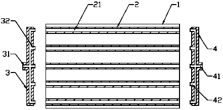
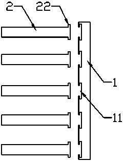
[0015] Such as figure 1 and figure 2 As shown, in this embodiment, the present invention includes a heat sink base plate 1 and a plurality of heat dissipation fins 2 arranged in parallel on the heat sink base plate 1, and deflectors 3 are respectively arranged on both sides of the heat dissipation fins 2 And the manifold 4, one side of the deflector 3 is provided with a total air inlet 31, and the other side is provided with some split air inlets 32 connected with the total air inlet 31, the manifold One side of 4 is provided with a general air outlet 41, and the other end is provided with a number of converging air outlets 42 connected with the general air outlet 41, and the middle parts of several of the cooling fins 2 are provided with cooling pipelines 21, the The split air inlet 32 ​​and the converging air outlet 42 are cooperatively connected with the cooling pipeline 21 , and the general air inlet 31 and the general air outlet 41 are both connected to an external liqu...


PUM


Abstract

The invention discloses a novel radiating fin, belongs to the technical field of radiating fins, and aims at providing the novel radiating fin reasonable in design, simple in structure and high in heat radiation efficiency. The radiating fin comprises a radiating fin base plate and radiating fins arranged on the base plate in parallel, a flow deflector and a cylinder manifold are arranged at the two sides of the radiating fins respectively, one side of the flow deflector is provided with a general air inlet, the other side of the flow deflector is provided with shunting air inlets communicatedwith the general air inlet, one side of the cylinder manifold is provided with a general air outlet, the other end of the cylinder manifold is provided with converging air outlets communicated with the general air outlet, cooling pipelines are arranged in the middle portions of the radiating fins respectively, the shunting air inlets and the converging air outlets are in cooperative connection with the cooling pipeline, and the general air inlet and the general air outlet are connected with an external liquid nitrogen pump via a gas pipe.

Description

technical field [0001] The invention relates to the technical field of heat sinks, in particular to a novel heat sink. Background technique [0002] The heat sink is a device for cooling the heat-prone electronic components in electrical appliances. It is mostly made of aluminum alloy, brass or bronze into plates, sheets, and multi-sheets. For example, the CPU central processing unit in a computer needs to use a large The heat sink in the TV, the power tube in the TV, and the power amplifier tube in the power amplifier must use heat sinks. [0003] The heat sink plays an important role in the composition of the heat sink. In addition to the active heat dissipation of the fan, the evaluation of a heat sink depends largely on the heat conduction capacity of the heat sink itself. Fins are an important part of heat sinks, and the heat transfer process of heat sinks is mainly completed by fins. [0004] In the prior art, heat sinks are used to dissipate heat through the thermal...

Claims


Application Information

Patent Timeline
IPC IPC(8): H05K7/20
CPCH05K7/20327H05K7/20372
Inventor 马昌发张全马向阳
Owner 珠海腾鑫精密五金制造有限公司
Learn More