Forged material conveying device for stamping steel balls

A conveying device and steel ball technology, applied in forging/pressing/hammer devices, operating devices, engine components, etc., can solve the problems of stamping forming efficiency and even the impact of the entire production capacity, slow reciprocating movement speed of sliding table, high equipment cost, etc., to achieve Ideal automation effect, reduce daily use and maintenance costs, and fast reciprocating sliding speed

Pending Publication Date: 2018-07-27
CHANGSHU FEIFAN METALWORK
View PDF12 Cites 7 Cited by
  • Summary
  • Abstract
  • Description
  • Claims
  • Application Information

AI Technical Summary

Problems solved by technology

[0004] In the prior art, the screw (also known as the lead screw) is generally driven by the servo motor and the sliding table is driven by the screw, that is, the worktable reciprocates between the cutting station and the punching station. The clamping device clamps the forging material (that is, "steel ball billet", the same below), and releases the forging material at the punching station. Therefore, only suitable stamping machines can be used, which will affect the stamping efficiency and even the entire production capacity; due to the relatively high cost of equipment controlled by servo motors, the cost of use and daily maintenance is high, so it is uneconomical
[0005] In the published Chinese patent literature, it can be seen that all the technical information applicable to the conveying device for conveying the aforementioned forging materials, such as CN203109155U recommends "a device for conveying workpieces for forging presses", and CN102581197A provides "conveyor for hot forging production line" "Manipulator" is not limited to these two patents. Although the two patents can embody the technical effects recorded in the technical effect column of the specification, they all use servo motors, so there are disadvantages mentioned by the applicant above.

Method used


Image

  • Forged material conveying device for stamping steel balls
  • Forged material conveying device for stamping steel balls

Examples


Embodiment Construction

[0021] In order to understand the technical essence and beneficial effects of the present invention more clearly, the applicant will describe in detail the following examples, but the descriptions of the examples are not intended to limit the solutions of the present invention. Equivalent transformations that are only formal but not substantive should be regarded as the scope of the technical solution of the present invention.

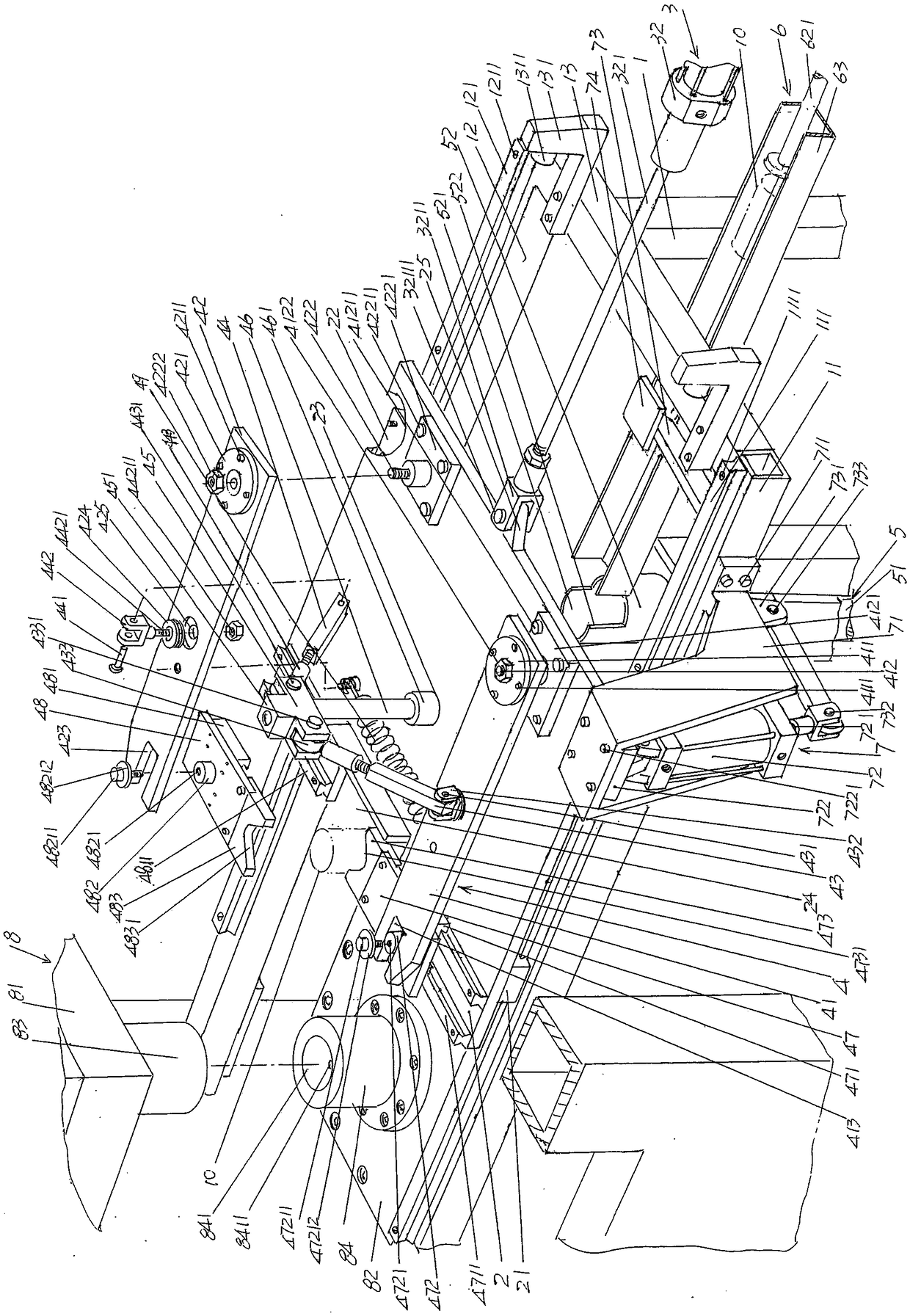
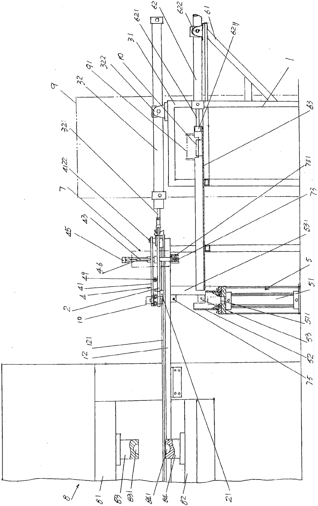
[0022] In the following descriptions, all concepts related to directionality or orientation of up, down, left, right, front and back are based on figure 1 with figure 2 As far as the position and state of the present invention are concerned, it cannot be understood as a special limitation on the technical solution provided by the present invention.

[0023] See figure 1 with figure 2 , shows a slide table frame 1; shows a slide table 2, and the slide table 2 is arranged on the upper part of the aforementioned slide table frame 1 in a reciprocating...


PUM


Abstract

The invention discloses a forging material conveying device for stamping steel balls, and belongs to the technical field of auxiliary equipment for steel ball stamping and forming. The conveying device comprises a sliding table machine frame, a sliding table, a pneumatic sliding table driving mechanism, a forging material clamping and releasing mechanism, a forging material pushing and feeding mechanism, a forging material pushing mechanism and a clamping driving mechanism, wherein the sliding table is arranged on the sliding table machine frame, the pneumatic sliding table driving mechanism is arranged on the right side of the sliding table machine frame and is connected to the sliding table, the forging material clamping and releasing mechanism is arranged on the sliding table, the forging material pushing and feeding mechanism is fixed to the sliding table machine frame at a position corresponding to the left side of the sliding table machine frame, the forging material pushing mechanism is arranged on the pneumatic sliding driving mechanism in a state corresponding to the forging material pushing and feeding mechanism and is further connected to the sliding table machine frame,and the clamping driving mechanism is fixed to the front side or rear side of the sliding table machine frame and extends to the position below the sliding table to correspond to the forging materialclamping and releasing mechanism. The conveying device has the advantages that the reciprocating sliding speed of the sliding table is high, and the forging material conveying efficiency can be improved; the reliability of the forging material clamping and releasing mechanism, arranged by taking the sliding table as a carrier, for clamping and releasing a forging material can be guaranteed; the economic performance of equipment can be embodied, and the daily use, inspection and protection cost can be lowered; and the automatic effect is ideal.

Description

technical field [0001] The invention belongs to the technical field of auxiliary equipment for stamping and forming steel balls, and in particular relates to a forging material conveying device for stamping steel balls. Background technique [0002] The process of steel ball stamping forming is: introduce the steel round bar into the heating furnace for heating, cut the heated steel round bar into forging material (also called "steel ball billet") according to the volume of the steel ball to be formed, and the forging material is passed through The conveying device is sent to the stamping machine to be punched into steel balls (through the steel ball forming die configured on the stamping machine). [0003] It can be seen from the above description that the forging material conveying device is the steel ball billet conveying device and is installed between the steel round bar cutting machine and the steel ball stamping forming machine under the use state; the stamping formin...

Claims


Application Information

Patent Timeline
Patent Type & Authority Applications(China)
IPC IPC(8): B21K1/02B21K27/02
CPCB21K1/02B21K27/02
Inventor 陈刚顾志文陆宇峰杨建平
Owner CHANGSHU FEIFAN METALWORK
Why Eureka
Try Eureka