
A device for continuous directional solidification of alloy castings with ultra-strong traveling wave magnetic field

A technology of directional solidification and traveling wave magnetic field, applied in the field of solidification equipment, can solve problems such as loss, and achieve the effect of eliminating shrinkage porosity, reducing cost and improving casting quality

Active Publication Date: 2019-12-31
HARBIN INST OF TECH
View PDF7 Cites 0 Cited by
  • Summary
  • Abstract
  • Description
  • Claims
  • Application Information

AI Technical Summary

Problems solved by technology

[0006] The purpose of the present invention is to solve the problem that the existing solidification equipment cannot effectively purify the alloy melt, eliminate segregation defects, eliminate shrinkage porosity, shrinkage cavity, and ensure the overall uniformity of alloy castings, as well as the casting problems caused by static gravity casting equipment. To solve the problem of material loss at the gate and runner, and provide a continuous processing directional solidification equipment for alloy castings with super strong traveling wave magnetic field

Method used


Image

  • A device for continuous directional solidification of alloy castings with ultra-strong traveling wave magnetic field
  • A device for continuous directional solidification of alloy castings with ultra-strong traveling wave magnetic field
  • A device for continuous directional solidification of alloy castings with ultra-strong traveling wave magnetic field

Examples


specific Embodiment approach 1

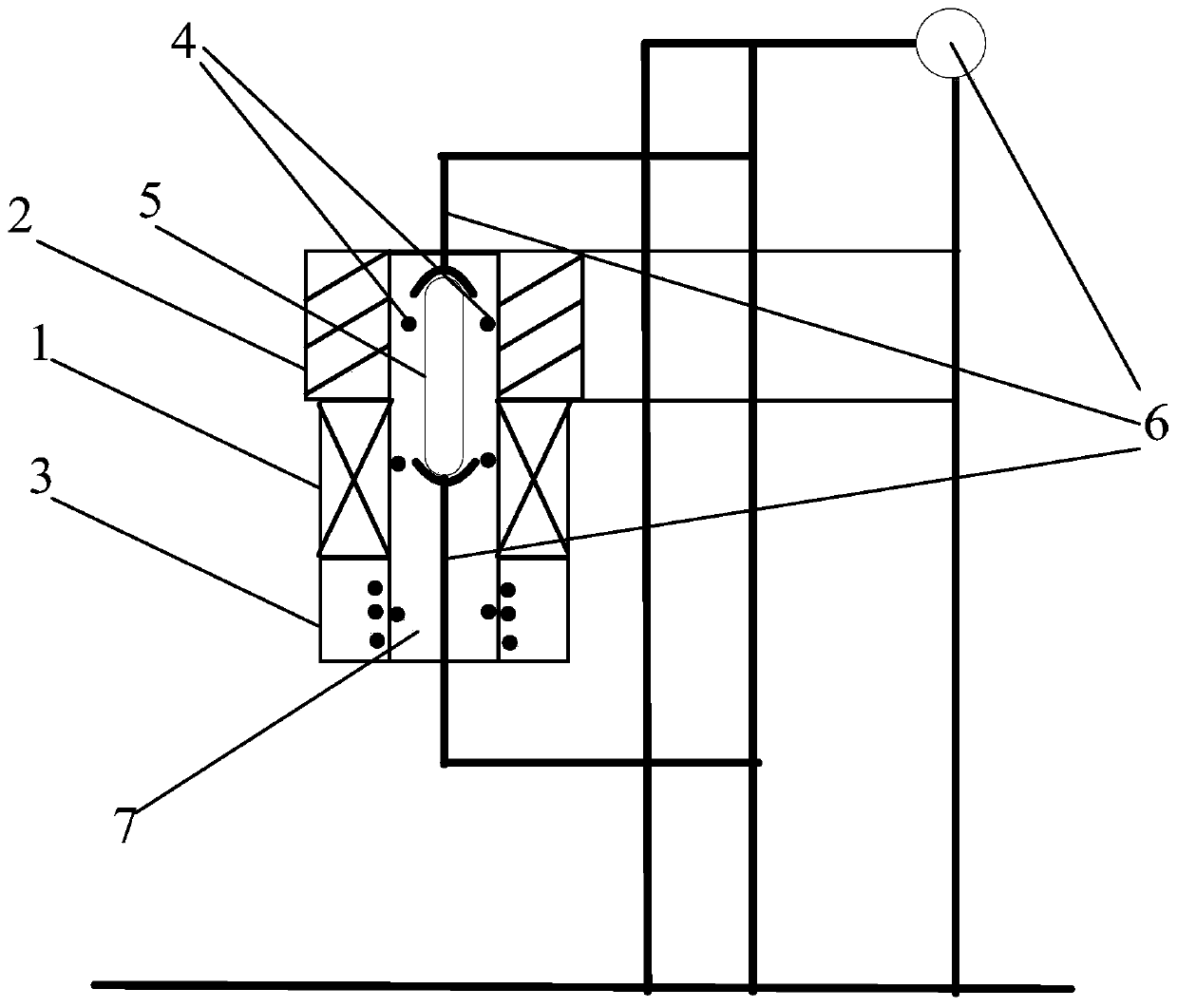
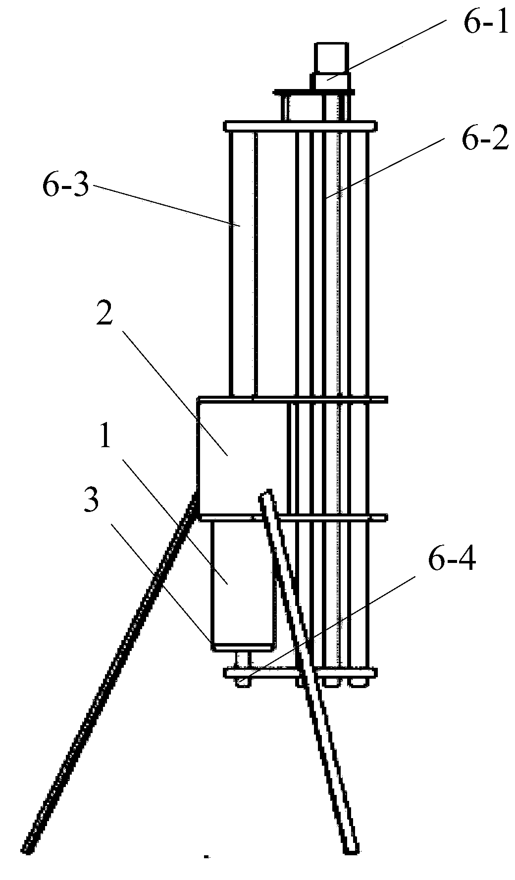
[0022] Specific implementation mode one: combine figure 1 and figure 2 Describe this embodiment, this embodiment comprises super-forced traveling wave magnetic field generating device (1), smelting and heat preservation device (2), cooling crystallization device (3), crucible (5), motor moving device (6) and several temperature measuring devices (4), the smelting and heat preservation device (2), the ultra-strong traveling wave magnetic field generating device (1) and the cooling and crystallization device (3) are arranged sequentially from top to bottom, the inner cavity of the smelting and heat preservation device (2), the super-forced The inner cavity of the wave magnetic field generating device (1) and the inner cavity of the cooling crystallization device (3) are a connected cavity (7), the crucible (5) is located in the cavity (7), and the crucible (5) and the motor The moving device (6) is connected, and several temperature measuring devices (4) are evenly distributed...

specific Embodiment approach 2

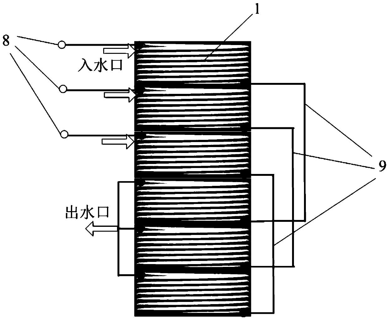
[0023] Specific implementation mode two: combination image 3 Describe the present embodiment, the present embodiment is that the ultra-forced traveling wave magnetic field generating device (1) is made up of six groups of coils, two of the six groups of coils are connected in series, and are connected to the three-phase power supply in a star connection, and the voltage, current and frequency can be adjusted The coil is made of hollow copper tube material, and the circulating cooling water is passed into the tube, and the water flow speed is controlled by the water pump, so as to control the cooling effect, integrate cooling and magnetism, and improve the working limit and working time of the super traveling wave magnetic field generating device (1). Achieve the acquisition of ultra-strong traveling wave magnetic field treatment. Other components and connections are the same as those in the first embodiment.

specific Embodiment approach 3

[0024] Specific implementation mode three: combination figure 1 Describe this embodiment, this embodiment is that the smelting and heat preservation device (2) is made of graphite heat preservation sleeve, and a resistance wire heating system is added in the graphite heat preservation sleeve, in order to melt the alloy in this area and ensure that the alloy melt is here higher temperature in the region. Other components and connections are the same as those in the second embodiment.


PUM


Abstract

The invention relates to solidification equipment, in particular to directional solidification equipment for continuous treatment of an ultra-strong traveling wave magnetic field of an alloy casting.The directional solidification equipment aims at solving the problems that existing solidification equipment cannot effectively and simultaneously meet the requirements of purifying an alloy melt, eliminating segregation defects, eliminating shrinkage porosity and shrinkage cavities, ensuring the overall uniformity of the alloy casting and the like as well as solving the problem of the material loss, caused by standing gravity casting equipment, at gates and runners. According to the directional solidification equipment, a smelting heat preservation device (2), an ultra-strong traveling wave magnetic field generating device (1) and a cooling crystallization device (3) are sequentially arranged from top to bottom, an inner cavity of the smelting heat preservation device (2), an inner cavityof the ultra-strong traveling wave magnetic field generating device (1) and an inner cavity of the cooling crystallization device (3) are a through mold cavity (7), a crucible (5) is positioned in the mold cavity (7), the crucible (5) is connected with a motor moving device (6), and multiple temperature measuring devices (4) are uniformly distributed at the upper, middle and lower positions of the mold cavity (7). The directional solidification equipment is used for forming the alloy casting used in the high-precision technical fields of automobiles, the military industry, aviation, aerospaceand the like.

Description

technical field [0001] The invention relates to a solidification device, in particular to a device for continuously processing alloy solid-liquid interface and alloy melt by super-strong traveling wave magnetic field during directional solidification process of alloy castings. Background technique [0002] At present, the traditional solidification equipment cannot effectively meet the requirements of purifying the alloy melt, eliminating segregation defects, eliminating shrinkage porosity, shrinkage cavity, and ensuring the overall uniformity of alloy castings; moreover, traditional static gravity casting equipment needs to design gates, pouring It is cumbersome and inconvenient to consider the pouring method, pouring gap and feeding pressure. In market applications, due to its complex process, cumbersome operation, low material utilization rate and high industrial cost, continuous automation of industrial production and market cannot be realized. Therefore, traditional met...

Claims


Application Information

Patent Timeline
Patent Type & Authority Patents(China)
IPC IPC(8): B22D27/02B22D27/04
CPCB22D27/02B22D27/045
Inventor 苏彦庆罗磊骆良顺王亮唐迎春蔡超军郭景杰
Owner HARBIN INST OF TECH
Learn More