Semi-automatic welding device for protecting cover of explosion-proof light

A semi-automatic welding and protective cover technology, applied in welding equipment, resistance welding equipment, metal processing equipment, etc., can solve the problems of slow processing speed, hidden safety hazards, poor positional accuracy of layout, etc.

Active Publication Date: 2018-07-27
威海鹏飞自动化技术有限公司
View PDF5 Cites 7 Cited by
  • Summary
  • Abstract
  • Description
  • Claims
  • Application Information

AI Technical Summary

Problems solved by technology

[0003] The traditional method of manufacturing explosion-proof lamp protective cover is generally all handmade. The position of each longitudinal rib and steel ring is manually laid out, and the welding torch with small current is used manually. The processing speed is very slow, and the position accuracy of the layout is poor. The protective cover of the explosion-proof lamp is not beautiful in appearance. After some installations are assembled, one side of the protective cover of the explosion-proof lamp is close to the luminous tube, and the other side is far away. If other equipment accidentally touches the protective cover of the explosion-proof lamp On the other hand, the protective cover of the explosion-proof lamp is squeezed on the luminous tube with a small deformation, which may cause damage to the luminous tube, and there is a large potential safety hazard
[0004] With the development of society, people pay more and more attention to occupational health, and fewer and fewer young people are unwilling to engage in electric welding work, because the fume of manual electric welding is harmful to human body, which leads to higher and higher salaries of electric welders , Recruitment is becoming more and more difficult, causing great pressure on labor companies

Method used


Image

  • Semi-automatic welding device for protecting cover of explosion-proof light
  • Semi-automatic welding device for protecting cover of explosion-proof light
  • Semi-automatic welding device for protecting cover of explosion-proof light

Examples


Embodiment

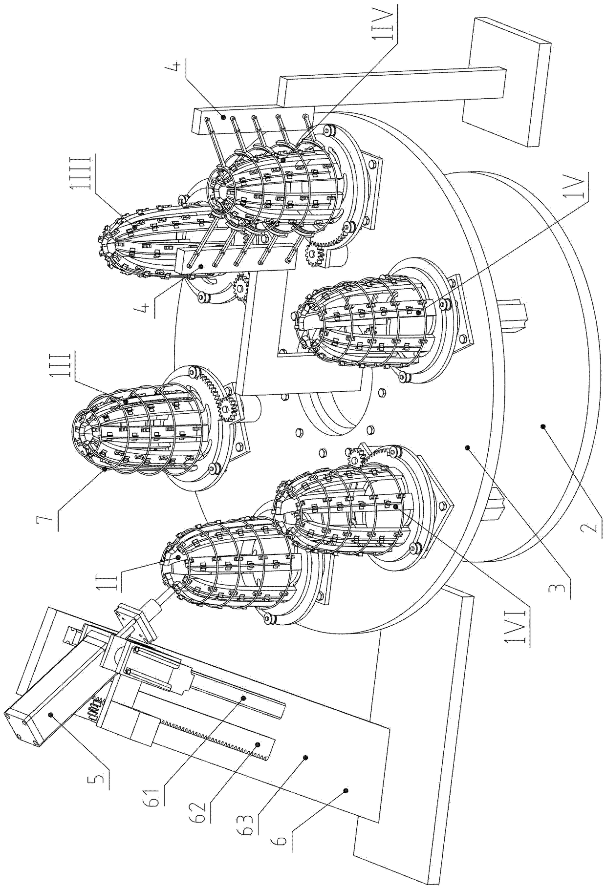
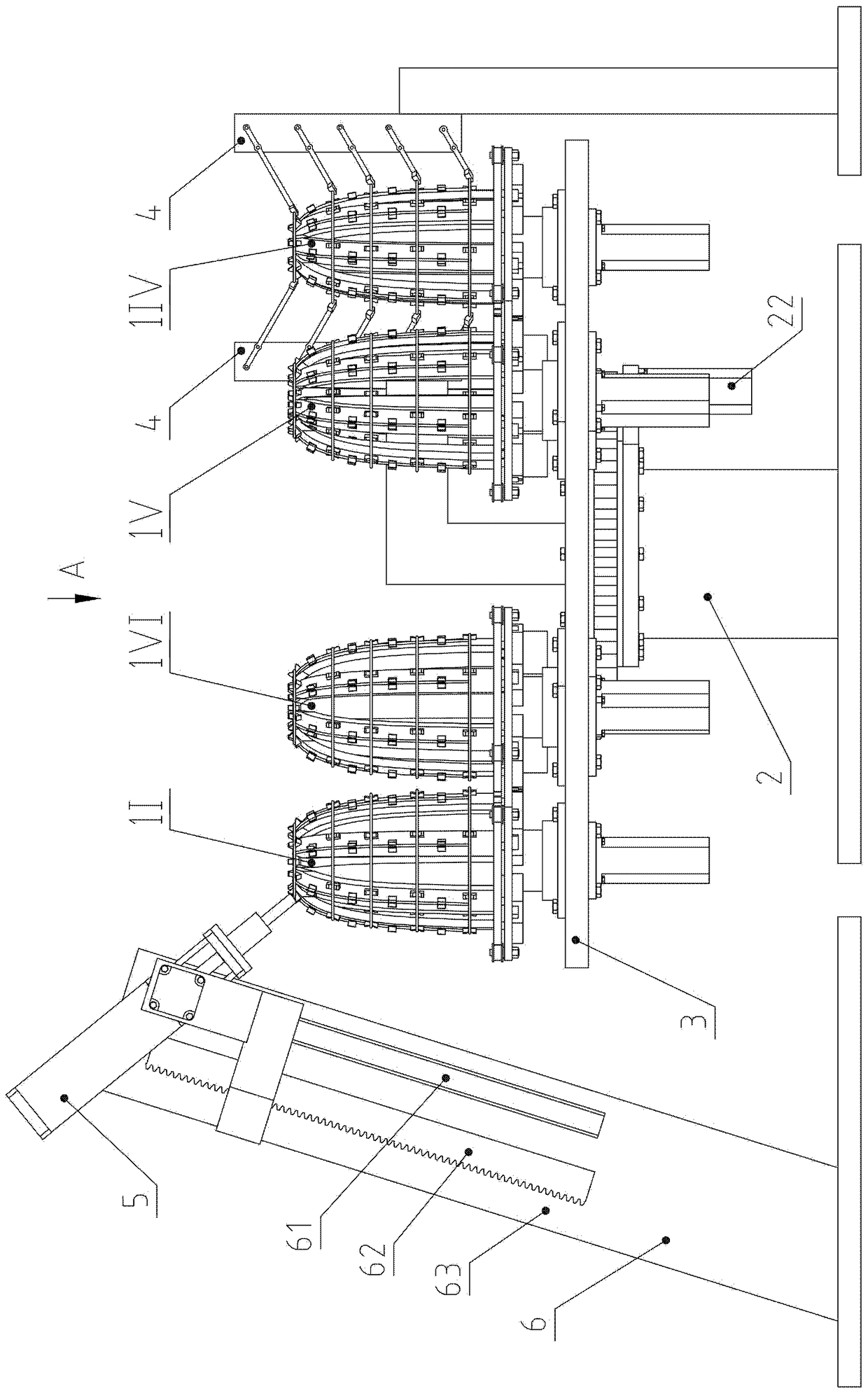
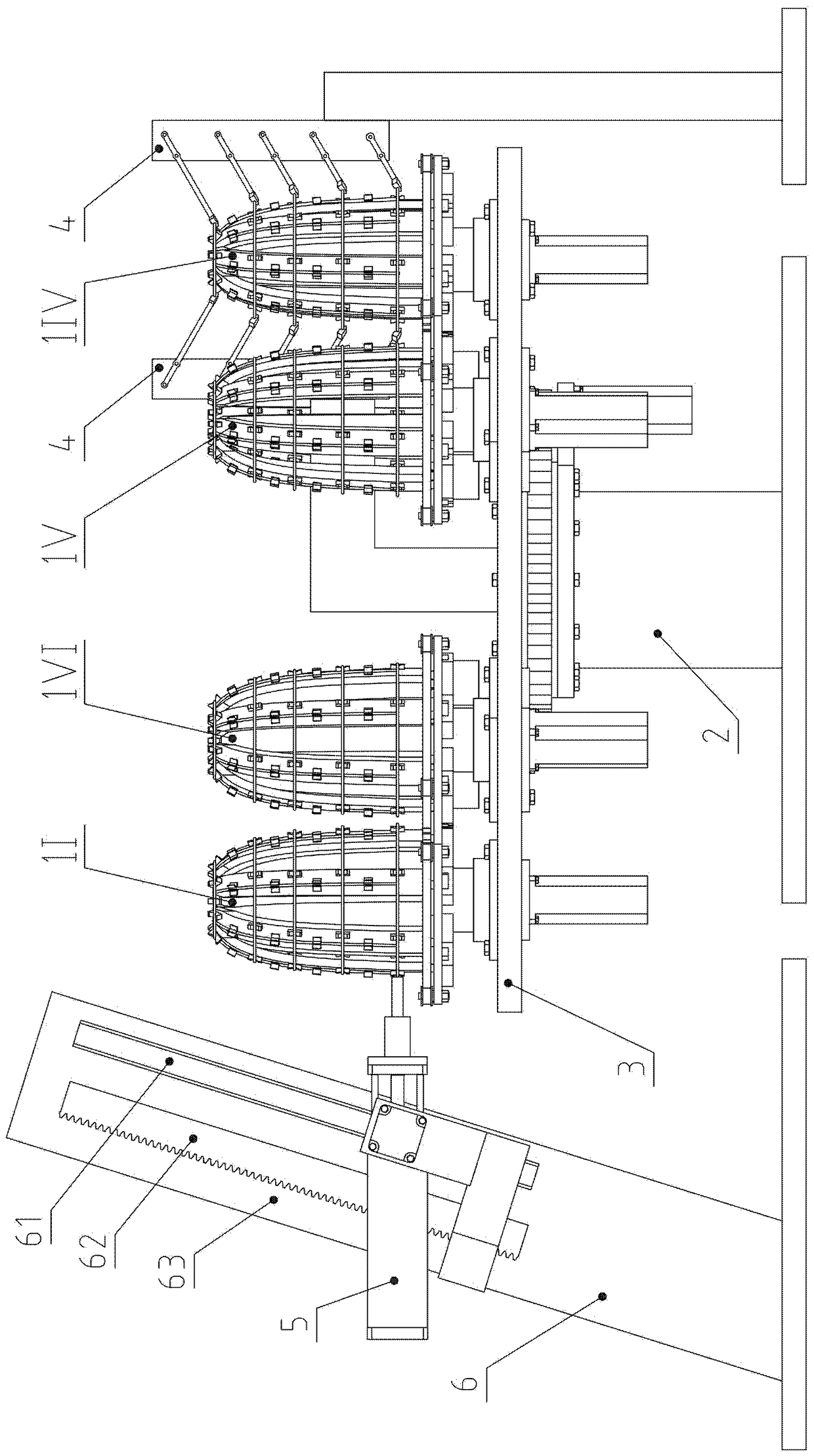
[0061] Example: see Figure 1 to Figure 19 .

[0062] A semi-automatic welding equipment for an explosion-proof lamp protective cover, including six mold assemblies 1, a turntable base assembly 2, a slewing bearing 8, a large turntable 3, two steel ring support assemblies 4, an electrode assembly 5, an electrode lifting frame 6 and welding power supply;

[0063] Six tire components 1 include No. I tire 1I, II tire 1II, III tire 1III, IV tire 1IV, V tire 1V and VI tire 1VI; six mold components 1 have The same shape structure and different station positions;

[0064] The mold assembly 1 includes seven curved surface support plate assemblies, a curved groove disc 12, a planetary wheel 13, a radial groove disc 14, a pinion 16, a split servo motor 17, a bearing 18 and a rotation servo motor 19;

[0065] The seven curved spreader assemblies are respectively curved spreader assembly 1 111, curved spreader assembly 2 112, curved spreader assembly 3 113, curved spreader assembly 4 1...


PUM


Abstract

The invention belongs to the technical field of explosion-proof tool manufacturing equipment, relates to a manufacturing device for a protecting cover of an explosion-proof light, and specifically relates to a semi-automatic welding device for the protecting cover of the explosion-proof light. The device is characterized in that longitudinal ribs are manually mounted on a curved supporting plate assembly; mould assemblies are automatic to rotate; the curved supporting plate assembly faces an operator; steel rings are manually mounted and positioned through steel ring positioning grooves; a curve slot disc is capable of synchronously shifting seven round shifting pins; seven mould assemblies are automatically expanded and fixed; revolution servo motors are used for driving to realize station switching; compressing cylinders are automatically lifted and swung in place; intersection points of the longitudinal ribs and the steel rings are compressed through high-voltage electrodes; then power supply is connected; the positions of the intersection points are automatically exchanged, and the spot welding is performed; the seven mould assemblies are automatically closed; and then a finished product is manually taken out. With the adoption of the device, the welding efficiency and the outline dimension accuracy are improved; the labor is saved; electric welding workers are saved, so that the salary cost is decreased, and the employment pressure is reduced.

Description

technical field [0001] The invention belongs to the technical field of explosion-proof equipment manufacturing equipment, and relates to a manufacturing equipment for an explosion-proof lamp protective cover, in particular to a semi-automatic welding equipment for an explosion-proof lamp protective cover. Background technique [0002] Explosion-proof lamps refer to lamps that are used in hazardous places where flammable gases and dust exist, and can prevent arcs, sparks and high temperatures that may be generated inside the lamp from igniting flammable gases and dust in the surrounding environment, thereby meeting explosion-proof requirements. In order to prevent accidental contact with the luminous tube of the explosion-proof lamp during construction, an explosion-proof lamp protective cover is often arranged around the luminous tube. The protective cover of the explosion-proof lamp includes longitudinal rib 1, longitudinal rib 2, longitudinal rib 3, longitudinal rib 5. Lon...

Claims


Application Information

Patent Timeline
Patent Type & Authority Applications(China)
IPC IPC(8): B23K11/00B23K11/36B23K101/22
CPCB23K11/002B23K11/36
Inventor 不公告发明人
Owner 威海鹏飞自动化技术有限公司
Why Eureka
Try Eureka