
Laser cutting machine

A laser cutting machine, servo motor technology, applied in laser welding equipment, welding equipment, metal processing equipment and other directions, can solve the problems of poor cutting effect, single training, inconvenient to adjust the height of the laser cutting head, etc., to achieve convenient and stable placement, convenient effect used

Inactive Publication Date: 2018-07-27
杭州勇冠网络科技有限公司
View PDF1 Cites 7 Cited by
  • Summary
  • Abstract
  • Description
  • Claims
  • Application Information

AI Technical Summary

Problems solved by technology

The structure of the laser cutting machine is complicated, which affects the exercise effect, low safety, and single training
[0003] For example, the patent application publication number CN205904584U discloses a laser cutting machine. The present invention includes a cutting machine, a laser, a laser guide rail, a controller, a laser cutting machine body, a beam, a laser cutting head, a first lens fixed end, a first lens, The second lens, the sliding body of the cutting machine, the sliding groove of the cutting machine, the pulley of the cutting machine, and the chute, but this device is inconvenient to move the laser cutting head flexibly, the cutting effect is poor, and it is inconvenient to adjust the height of the laser cutting head. Dust generated by cutting is collected and processed

Method used


Image

  • Laser cutting machine
  • Laser cutting machine
  • Laser cutting machine

Examples


Embodiment Construction

[0020] The following will clearly and completely describe the technical solutions in the embodiments of the present invention with reference to the accompanying drawings in the embodiments of the present invention. Obviously, the described embodiments are only some, not all, embodiments of the present invention. Based on the embodiments of the present invention, all other embodiments obtained by persons of ordinary skill in the art without making creative efforts belong to the protection scope of the present invention.

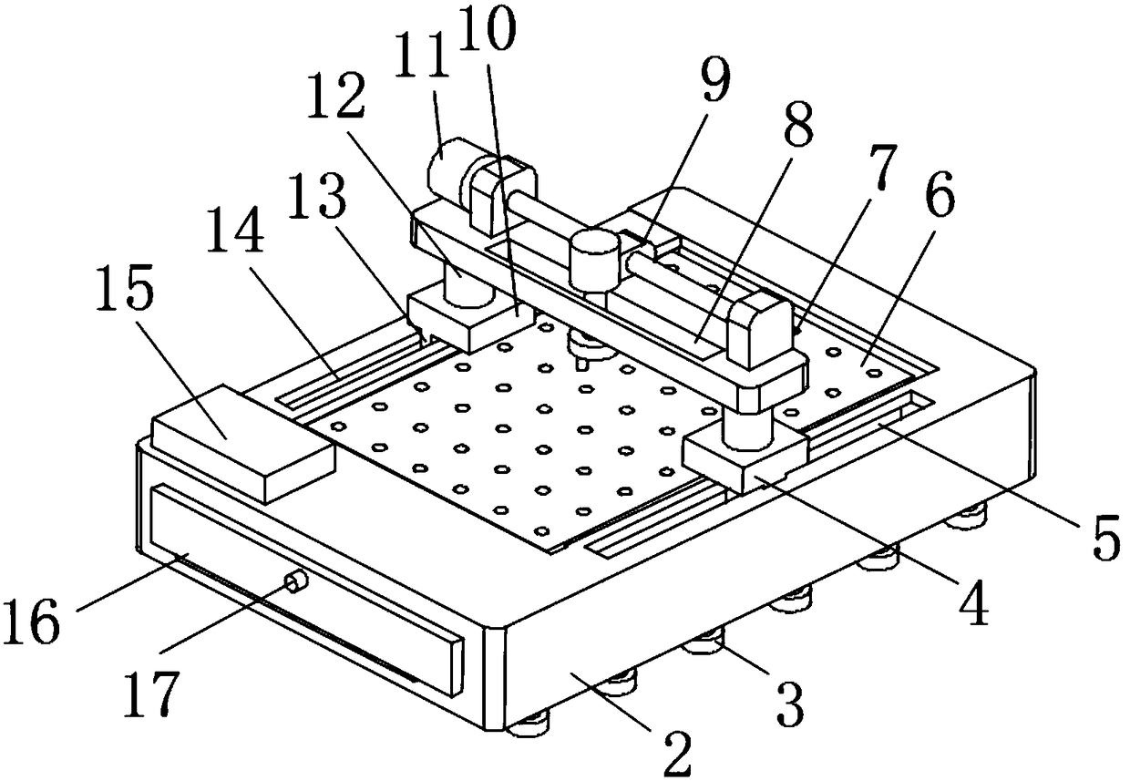
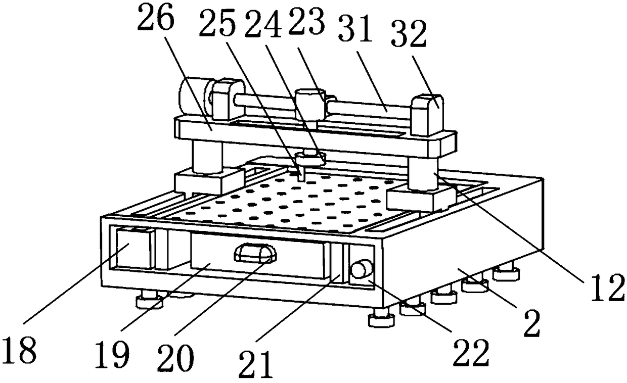
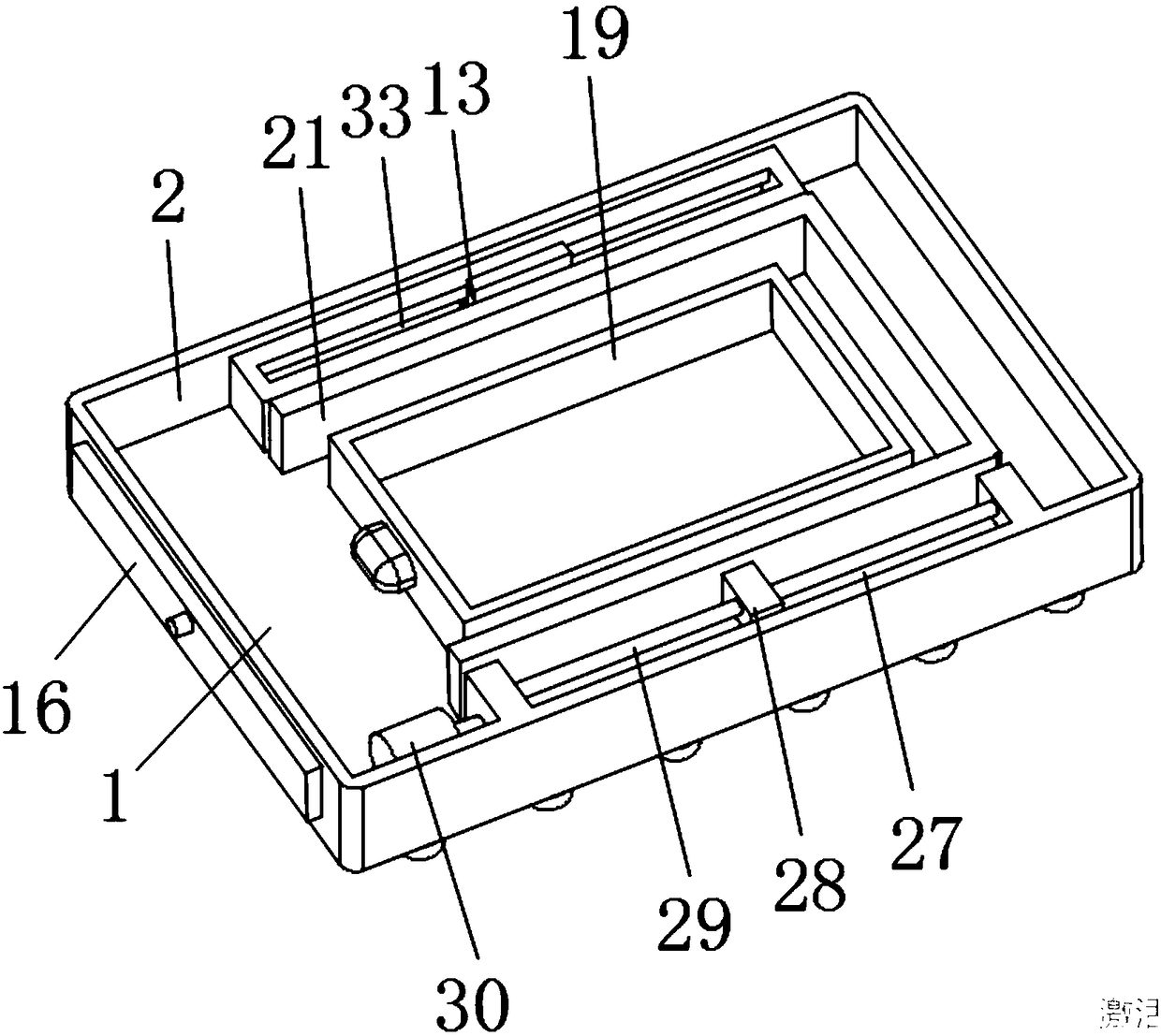
[0021] see Figure 1-3 , the present invention provides a technical solution: a laser cutting machine, including a base plate 1, the upper surface of the base plate 1 is provided with a bracket 21, the upper surface of the bracket 21 is provided with a placement plate 6, and the upper surface of the base plate 1 is located near the front side Two fixed plates-22 are provided, and a guide rod 29 fixedly connected with the fixed plate-22 is provided between the ...


PUM


Abstract

The invention discloses a laser cutting machine. The laser cutting machine comprises a bottom plate, the upper surface of the bottom plate is provided with a bracket, the upper surface of the bracketis provided with a storing plate, and two first fixing plates are arranged at the positions, close to the front side face, of the upper surface of the bottom plate; a guiding rod fixedly connected with the first fixing plates is arranged between the two first fixing plates, a first lead screw is mounted between the two first fixing plates through a bearing in a matched mode, and the first lead screw is connected with a second sliding block through a lead screw nut; and the first lead screw is in threaded connection with a screw hole in the second sliding block, and the guiding rod penetrates through a through hole in the side face of the second sliding block. According to the laser cutting machine, stable moving of a laser cutting head in the horizontal direction is achieved through the first lead screw and a second lead screw, the height of the laser cutting head is adjusted through an electric telescopic rod, using is convenient, micro-movement of the laser cutting head is achieved through a second servo motor, collecting treatment is conducted on dust produced during cutting is achieved through a garbage hole and a collecting box, and stable placing of the laser cutting machineis facilitated through foot pads.

Description

technical field [0001] The invention relates to the technical field of cutting machines, in particular to a laser cutting machine. Background technique [0002] Laser cutting is to focus the laser emitted from the laser into a high power density laser beam through the optical path system. The laser beam irradiates the surface of the workpiece to make the workpiece reach the melting point or boiling point, and at the same time, the high-pressure gas coaxial with the beam blows away the molten or vaporized metal. With the movement of the relative position of the beam and the workpiece, the material will eventually form a slit, so as to achieve the purpose of cutting. At present, the structure of the known laser cutting machine is that the laser cutting machine generally includes the main body of the cutting machine, the bottom plate of the cutting machine, a support frame, a support rod, a fixing device, a power interface and other components. The laser cutting machine has a...

Claims


Application Information

Patent Timeline
IPC IPC(8): B23K26/38B23K26/08B23K26/16B23K26/70
CPCB23K26/38B23K26/0884B23K26/16B23K26/702
Inventor 赖传柏
Owner 杭州勇冠网络科技有限公司
Learn More