Tray

A technology of pallets and beams, applied in the direction of lifting devices, etc., can solve problems such as increased operational difficulty, interlude cargo, and pallet function constraints, and achieve the effects of reducing loading and unloading labor costs, reducing packaging damage, and reducing shipping costs

Pending Publication Date: 2018-07-27
刘通
View PDF0 Cites 2 Cited by
  • Summary
  • Abstract
  • Description
  • Claims
  • Application Information

AI Technical Summary

Problems solved by technology

[0003] 1. Limited by the transmission of continuous automatic packaging production lines, most of the pallets used now are double-sided flat pallets, and the functions of the pallets are restricted
[0004] 2. Since the pallet is a reusable item, it must be separated from the product before the product is loaded. The structure of the existing general-purpose double-sided pallet is limited, and it is impossible to directly insert the goods on the pallet with a forklift to separate them.
[0005] 3. Due to the various forms of transportation vehicles, there are various transportation tools such as containers, flatbed trucks, and trains, and the sizes of the carriages are different. Due to the constraints of the existing pallets, it cannot meet the requirements of mechanized loading work at the same time
It is necessary to install attachments with flipping and pushing functions on different forklifts to solve the problem of loading and unloading trucks for different vehicles, increase the tonnage and single operation requirements of forklifts, increase the number of forklifts, and reduce the utilization rate of forklifts
At the same time, the conversion operation needs to be performed through the conversion pallet, which increases the difficulty of the operation, reduces the efficiency, and increases the operation risk of the operator.
Bags are also often dropped during the conversion process, resulting in damaged packaging

Method used


Image

  • Tray
  • Tray
  • Tray

Examples


Embodiment Construction

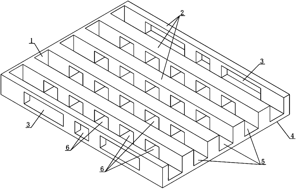
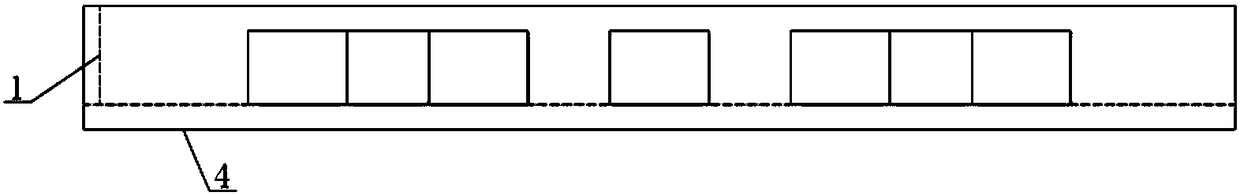
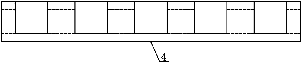
[0020] The pallet of the present invention is a tool for the operation of handling and unloading equipment, and has a bottom plate 4, which is a flat plate, so that the pallet can be passed through the automatic packaging line, and can also isolate the upper and lower layers of goods, so that the overall stability of the pallet is good; the bottom plate There are 6 parallel beams 2 (corresponding to the number of forks of the forklift) on the top, and the groove-shaped passage 5 formed between the beams is convenient for the insertion of the forks of the forklift; each beam is provided with a through hole 6 in the vertical direction. The adjacent through holes are opposite to each other. Among them, there are 3 through holes on the beam on the side of the bottom plate, and the through holes at both ends are large through holes 3. The large through holes correspond to the positions of the pallet forks on the automatic packaging machine. Other beams are equipped with 5 through ho...


PUM


Abstract

The invention discloses a tray, and belongs to a tool which cooperates with a forklift for use and operates from a continuous automatic packaging production line to carrying, loading and unloading equipment. The tray has the technical characteristics of being provided with a bottom plate, wherein a plurality of parallel cross beams are arranged on the bottom plate, a groove-shaped channel is formed between every two cross beams, and a plurality of through holes are formed in each cross beams; every two adjacent through holes of every two adjacent cross beams are opposite, the opposites through holes form channels perpendicular to the direction of the cross beams, and one end of each cross beam is connected with a side plate; and the through holes formed in the two ends of each of the twocross beams located on the outer side of the bottom plate are large through holes, each large through hole is opposite to the two through holes formed in the cross beam adjacent to another cross beamwhere the corresponding large through hole is located, and the cross section size of each through hole and the cross section size of the groove between every two cross beams are larger than the maximum size of the cross section of a fork of the forklift. By using the tray, mechanization of the whole process of carrying, loading and unloading can be realized, and the labor cost and the safety riskof operation are reduced.

Description

technical field [0001] The invention relates to a pallet, which is a tool for mechanical equipment operation in cooperation with a continuous automatic packaging production line and in the process of handling and loading and unloading. Background technique [0002] The traditional pallet used on the production line is a general-purpose double-sided flat pallet. After loading the goods, a general-purpose two-fork forklift is required to carry out off-line operations because the pallet has only two insertion ports. During the loading operation, a forklift is required to pick up the goods to the nearest point of unloading. After unloading the goods manually or using machinery to turn over the product materials and pallets as a whole, the pallets are converted and then pushed out by the forklift pusher. Its flaws are: [0003] 1. Limited by the transmission of continuous automatic packaging production lines, most of the pallets used today are double-sided flat pallets, and the ...

Claims


Application Information

Patent Timeline
Patent Type & Authority Applications(China)
IPC IPC(8): B66F9/12
CPCB66F9/12
Inventor 刘通
Owner 刘通
Why Eureka
Try Eureka