Supercharge Your Innovation With Domain-Expert AI Agents!

Spherical robot visual positioning system

A spherical robot, visual positioning technology, applied in the direction of navigation calculation tools, etc., can solve the problems of time drift error, unusable, difficult to find the position of the odometer, achieve accurate positioning, solve the problem of constant installation, improve efficiency and accuracy degree of effect

Inactive Publication Date: 2018-07-27
QUZHOU COLLEGE OF TECH
View PDF5 Cites 7 Cited by
  • Summary
  • Abstract
  • Description
  • Claims
  • Application Information

AI Technical Summary

Problems solved by technology

At present, spherical robots mainly use inertial navigation system, odometer, GPS and other methods for positioning, but the inertial navigation system needs to obtain the displacement and angle through integration, and there is a time drift error; the odometer will produce cumulative errors due to spherical sliding, jumping and other factors , at the same time, the spherical robot platform is unstable, and it is difficult to find a suitable position for carrying the odometer; the GPS accuracy is not high, and it cannot be used indoors
The outside of the spherical robot is a closed spherical shell, and the image quality collected by the camera through the spherical shell is very poor or even impossible to collect images
Difficult to install the camera, the usual installation position will make the camera rotate 360 ​​degrees with the ball

Method used


Image

  • Spherical robot visual positioning system

Examples


Embodiment Construction

[0027] In order to make the objects and advantages of the present invention clearer, the present invention will be further described in detail below in conjunction with the examples. It should be understood that the specific embodiments described here are only used to explain the present invention, not to limit the present invention.

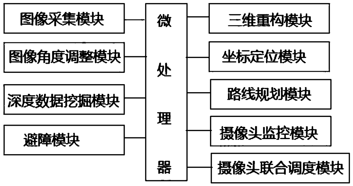
[0028] like figure 1 As shown, the embodiment of the present invention provides a spherical robot vision positioning system, including

[0029] The image acquisition module collects image data through N fisheye lenses with gyroscopes evenly installed on the spherical robot; and sends the collected image data to the image angle adjustment module;

[0030] The image angle adjustment module is used to determine the deflection angle of each image according to the data collected by the gyroscope, reconstruct the other images according to the deflection angle of one of the images, and send the processed image to the deep data mining module ; Complet...


PUM


Abstract

The invention discloses a spherical robot visual positioning system. The spherical robot visual positioning system comprises an image acquisition module, an image angular adjustment module, a depth data excavation module, a three-dimensional reconstruction module, a coordinate calibration module, a route programming module, an obstacle avoidance module, a camera monitoring module, and a camera combined scheduling module. Through adjustment of image angles, splicing reconstruction of the three-dimensional images is realized, accurate positioning of a target position is realized, real-time updated output of a target route is realized, positioning efficiency and accuracy are increased, during a motion process of the robot, combined scheduling is realized according to the route programming byeach camera, when the real-time acquisition of the images is realized, and the problem of unchanged installation can be solved.

Description

technical field [0001] The invention relates to the field of robot positioning systems, in particular to a spherical robot vision positioning system. Background technique [0002] Spherical robot refers to a general term for a system that integrates motion actuators, sensors, controllers, and energy devices into a spherical shell and uses the spherical shell as a rolling walking device. Compared with wheeled, footed and tracked robots, it has the characteristics of novel structure, flexible movement and high efficiency, and has broad application prospects in military, civil and industrial fields. [0003] The positioning problem of spherical robot is a key problem to realize the intelligentization of spherical robot. At present, spherical robots mainly use inertial navigation system, odometer, GPS and other methods for positioning, but the inertial navigation system needs to obtain the displacement and angle through integration, and there is a time drift error; the odometer...

Claims


Application Information

Patent Timeline
IPC IPC(8): G01C21/20
CPCG01C21/20
Inventor 魏小华徐建亮巫少龙张晨恺
Owner QUZHOU COLLEGE OF TECH
Features
  • R&D
  • Intellectual Property
  • Life Sciences
  • Materials
  • Tech Scout
  • Unparalleled Data Quality
  • Higher Quality Content
  • 60% Fewer Hallucinations
Learn More