Type I crack specimen dynamic symmetrical tensile device for and experimental method thereof
A technology of stretching device and crack, which is applied in the field of materials, can solve the problems such as the difficulty of achieving the symmetry of the loading force, and achieve the effect of ensuring the synchronization of the waveform
- Summary
- Abstract
- Description
- Claims
- Application Information
AI Technical Summary
Problems solved by technology
Method used
Image
Examples
Embodiment 1
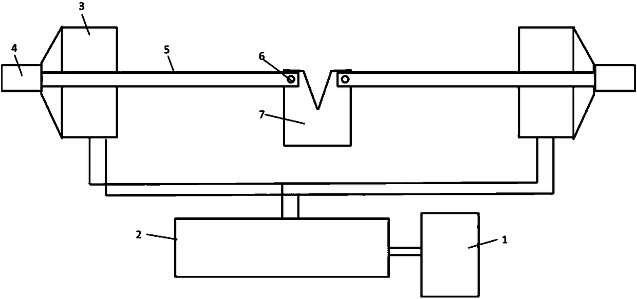
[0067] Such as figure 1 As shown, this embodiment is a dynamic symmetrical tensioning device for standard compact tensile samples based on electromagnetic force. The loading device described in the Chinese invention patent with the patent number ZL 201510956545.4 is used, including a power supply 1 , capacitor charger 2 and loading gun 3. The capacitor charger 2 adopts the power supply part of the existing electromagnetic riveting equipment. After connecting two loading guns 3 with identical parameters in parallel, they are connected to the capacitor charger 2 . The power supply 1 adopts a three-phase alternating current of 220 volts (V).
[0068]In this embodiment, the capacitor charger 2 adopts the power supply part of the electromagnetic riveting equipment disclosed in the Chinese patent No. 200520079179. In this embodiment, the three rated voltages are 5000 volts and the rated capacitance is 2 millifarads. The pulse capacitors are connected in parallel to form a capacit...
Embodiment 2
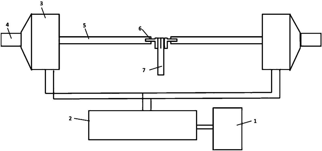
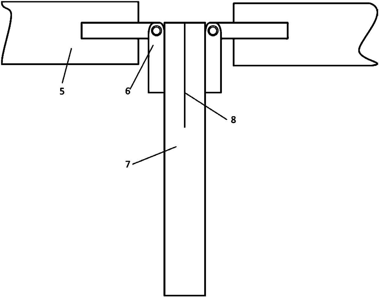
[0081] Such as figure 2 with 3 As shown, this embodiment is a dynamic symmetrical tensile device for double cantilever beam samples based on electromagnetic force. The loading device described in the Chinese invention patent with the patent number ZL 201510956545.4 is used, including a power supply 1, Capacitor charger 2 and loading gun 3. The capacitor charger 2 adopts the power supply part of the existing electromagnetic riveting equipment. After connecting two loading guns 3 with identical parameters in parallel, they are connected to the capacitor charger 2 . The power supply 1 adopts 220V three-phase alternating current.
[0082] In this embodiment, the capacitor charger 2 adopts the power supply part of the electromagnetic riveting equipment published in the Chinese patent No. 200520079179. In this embodiment, the six rated voltages are 5000 volts and the rated capacitance is 2 millifarads. The pulse capacitors are connected in parallel to form a capacitor bank, and...
Embodiment 3
[0095] Such as Figure 4 As shown, this embodiment is a dynamic symmetrical tensioning device for a centrally penetrating crack sample based on electromagnetic force. The loading device is the loading device proposed in the Chinese invention patent with the patent number ZL 201510956545.4, including a power supply 1 , capacitor charger 2 and loading gun 3. The capacitor charger 2 adopts the power supply part of the existing electromagnetic riveting equipment. After connecting two loading guns 3 with identical parameters in parallel, they are connected to the capacitor charger 2 . The power supply 1 adopts 220V three-phase alternating current.
[0096] In this embodiment, the capacitor charger 2 adopts the power supply part of the electromagnetic riveting equipment disclosed in the Chinese patent No. 200520079179. In this embodiment, the three rated voltages are 5000 volts and the rated capacitance is 2 millifarads. The pulse capacitors are connected in parallel to form a ca...
PUM
| Property | Measurement | Unit |
|---|---|---|
| diameter | aaaaa | aaaaa |
| diameter | aaaaa | aaaaa |
| length | aaaaa | aaaaa |
Abstract
Description
Claims
Application Information
 - R&D
- Intellectual Property
- Life Sciences
- Materials
- Tech Scout
- Unparalleled Data Quality
- Higher Quality Content
- 60% Fewer Hallucinations
Browse by: Latest US Patents, China's latest patents, Technical Efficacy Thesaurus, Application Domain, Technology Topic, Popular Technical Reports.
© 2025 PatSnap. All rights reserved.Legal|Privacy policy|Modern Slavery Act Transparency Statement|Sitemap|About US| Contact US: help@patsnap.com


