
Drive test trajectory map display method and device

A display method and trajectory technology, which is applied in the direction of measuring devices, radio wave measurement systems, satellite radio beacon positioning systems, etc., can solve problems such as browser stuck, affecting user use, and large data volume, so as to reduce data volume, Improve display efficiency and user fluency, and ensure the uniqueness of results

Inactive Publication Date: 2018-07-27
SHANGHAI DATANG MOBILE COMM EQUIP
View PDF3 Cites 2 Cited by
  • Summary
  • Abstract
  • Description
  • Claims
  • Application Information

AI Technical Summary

Problems solved by technology

[0004] A trajectory is a line, which is composed of many points, and its shape is determined by several key inflection points. Since the GPS positioning information is affected by factors such as equipment, terrain, signal source strength, and surrounding environment, the coordinate information in the drive test data will change. Contains a lot of dirty data or even bad data, so most of the current methods are: after the drive test data is stored in the database, the data is preprocessed through the background, and then the front desk displays it directly, but the preprocessing of the data in the background generally only removes a small amount of abnormal data , such as the coordinate drift is too large, or the data of repeated coordinates is sent within a period of time, so when the front desk displays large data, it will be more difficult and the performance will decrease
Moreover, because the data sampling frequency of the road test track is high and the time is long, resulting in a large amount of data, when the road test track map is displayed on the front desk, the map will load slowly, the browser will freeze, and the user will be affected.

Method used


Image

  • Drive test trajectory map display method and device
  • Drive test trajectory map display method and device
  • Drive test trajectory map display method and device

Examples


Embodiment Construction

[0046] In order to make the purpose, technical solutions and advantages of the embodiments of the present invention clearer, the technical solutions in the embodiments of the present invention will be clearly and completely described below in conjunction with the drawings in the embodiments of the present invention. Obviously, the described embodiments It is only some embodiments of the present invention, but not all embodiments. Based on the embodiments of the present invention, all other embodiments obtained by persons of ordinary skill in the art without creative efforts fall within the protection scope of the present invention.

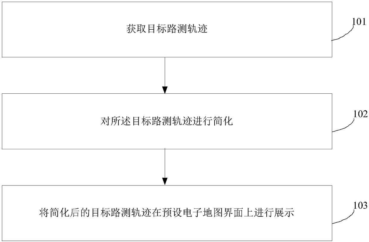
[0047] figure 1 It shows a schematic flowchart of a method for displaying a road test track map provided by an embodiment of the present invention, as shown in figure 1 As shown, the method for displaying the road test track map in this embodiment is as follows.

[0048] 101. Obtain a target drive test track.

[0049] In a specific application,...


PUM


Abstract

The invention provides a drive test trajectory map display method and device. The method comprises: a target drive test trajectory is obtained; the target drive test trajectory is simplified; and thesimplified target drive test trajectory is displayed on a preset electronic map interface. Therefore, the data volume of the drive test trajectory is reduced substantially; the display efficiency of the foreground drive test trajectory map and the usage smoothness of the user are improved; the features of the drive test trajectory are protected from being lost; and thus line feature unique and result unique principles of the drive test trajectory are ensured.

Description

technical field [0001] The invention relates to the technical field of computer data processing, in particular to a method and device for displaying a road test track map. Background technique [0002] During the drive test process, the drive test track can accurately identify the travel track of the test vehicle, identify the changes in signal coverage and service capabilities on the test path, and provide an identification function for locating the specific location of the network problem. [0003] The existing road test trajectory recording method mainly adopts the method of collecting GPS data reported by the GPS device when connecting to the traditional Global Positioning System (GPS) device and combining the collected parameters to perform trajectory management. [0004] A trajectory is a line, which is composed of many points, and its shape is determined by several key inflection points. Since the GPS positioning information is affected by factors such as equipment, t...

Claims


Application Information

Patent Timeline
Patent Type & Authority Applications(China)
IPC IPC(8): G01S19/42
Inventor 树志平赵本福
Owner SHANGHAI DATANG MOBILE COMM EQUIP
Learn More