Full-automatic spraying device for wind power bolts, and working method thereof

A technology for wind power bolts and spraying equipment, which is applied to coatings, spraying devices, and devices for coating liquid on surfaces, etc., can solve the problems of large volume, hidden safety hazards, and poor uniformity of wind power bolts, so as to avoid uneven spraying and spraying. Even, easy-glide effect

Active Publication Date: 2018-07-31
黄翔鸥
View PDF9 Cites 7 Cited by
  • Summary
  • Abstract
  • Description
  • Claims
  • Application Information

AI Technical Summary

Problems solved by technology

In recent years, there are more and more applications of Dacromet coating on the surface of wind power bolts. However, due to the large volume of wind power bolts, the existing coating equipment cannot meet the needs of automatic coating, so most of them are manually coated. Spraying, the uniformity is poor, the efficiency is low, because the dacromet solution contains chromium ions which are harmful to the human body, there are certain safety hazards

Method used


Image

  • Full-automatic spraying device for wind power bolts, and working method thereof
  • Full-automatic spraying device for wind power bolts, and working method thereof
  • Full-automatic spraying device for wind power bolts, and working method thereof

Examples


Embodiment 1

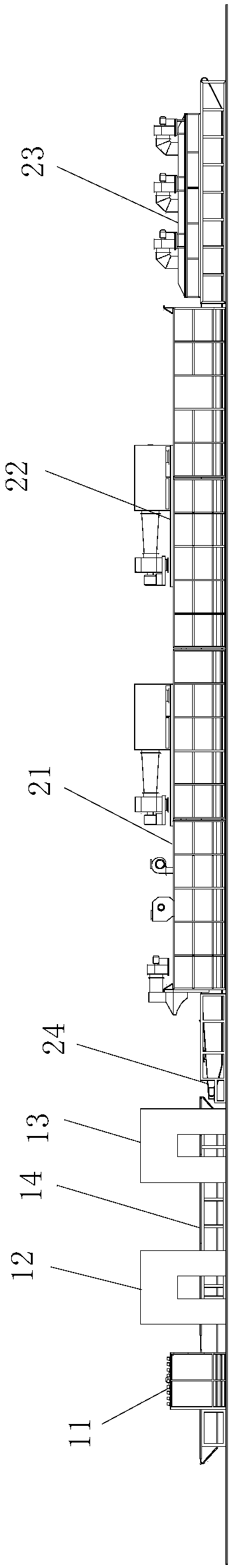
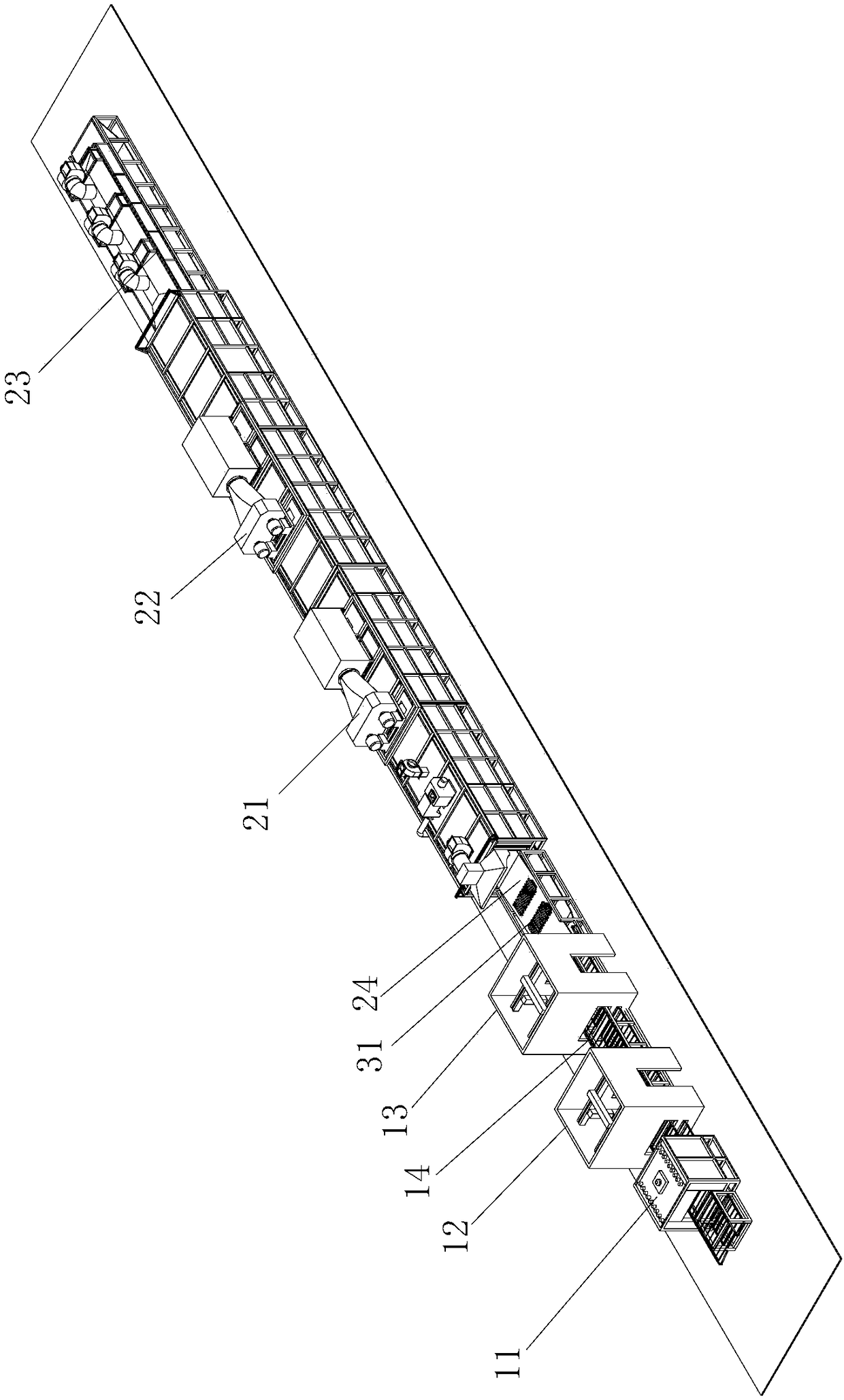
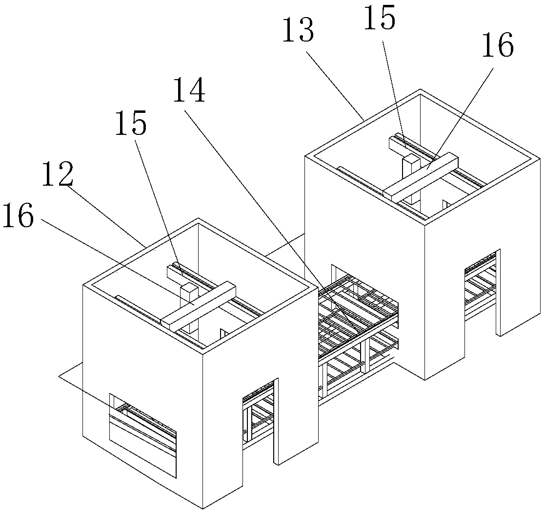
[0026] Example 1 as Figure 1 to Figure 2 As shown, the fully automatic spraying equipment for wind power bolts in this embodiment includes a preheating furnace 11, a first spraying device 12, a second spraying device 13, and a sintering furnace arranged in sequence, and the first conveyor network is arranged in the hearth of the preheating furnace 11. Belt 14, the first conveyor belt 14 passes through the preheating furnace 11 and extends to the bottom of the first spraying device 12 and the second spraying device 13, so as to spray the wind power bolts 31 preheated by the preheating furnace 11 ; The second conveyor belt 24 is set through the hearth of the sintering furnace, and the outlet of the first conveyor belt 14 is connected with the entrance of the second conveyor belt 24; as image 3 As shown, the first spraying device 12 comprises a spraying room, the first conveyor belt 14 passes through the spraying room and is provided with a slide rail 15 perpendicular to the fi...

Embodiment 2

[0029] A fully automatic spraying method for wind power bolts, comprising the following steps:

[0030] Step A, put the wind power bolt 31 to be sprayed on the material rack, the zigzag support plate 33 is in the initial state, the flat top 331 of the zigzag support plate 33 coincides with the concave wave trough 322 of the square wave support plate 32, multiple wind power The bolts 31 are sequentially arranged on the flat tops 331 of each zigzag support plate 33 .

[0031] Step B: Turn on the preheating furnace 11, place the material rack on the first conveyor belt 14 and pass through the preheating furnace 11, so that the surface temperature of the wind power bolt 31 after passing through the preheating furnace 11 is 45 to 55°C, and perform preheating. heat treatment.

[0032] Step C, the material rack on the first conveyor belt 14 and the wind power bolt 31 pass under the first spraying device 12, and the spray head 16 of the first spraying device 12 moves back and forth on ...


PUM


Abstract

The invention relates to a full-automatic spraying device for wind power bolts, and a working method thereof. The full-automatic spraying device for the wind power bolts comprises a preheating furnace, a first spraying device, a second spraying device and a sintering furnace arranged sequentially, and further comprises a first conveying mesh belt, a second conveying mesh belt, and a rack for placing the wind power bolts. The first conveying mesh belt penetrates through a hearth of the preheating furnace and further penetrates through the first spraying device and the second spraying device soas to be arranged below; the second conveying mesh belt penetrates through a hearth of the sintering furnace; an outlet of the first conveying mesh belt is connected with an inlet of the second conveying mesh belt; and the rack loaded with the wind power bolts is preheated through the preheating furnace, is sprayed through the first spraying device and the second spraying device, is conveyed through the second conveying mesh belt so as to enter the sintering furnace, and is sintered.

Description

technical field [0001] The invention relates to the technical field of dacromet coating equipment, in particular to a fully automatic spray coating equipment for wind power bolts and a working method thereof. Background technique [0002] As my country adjusts its energy structure and accelerates the implementation of the energy development strategy of developing renewable energy and improving the environment, wind power is widely used as a clean energy. my country's wind power industry, especially large-capacity megawatt-level large-scale wind turbines, has developed rapidly. High-strength fasteners used in wind power equipment are required to have strong stability due to long-term field service, harsh environment, and poor maintenance conditions. Among them, the most commonly used fasteners are wind power bolts. With the increase of installed capacity, in order to meet its performance requirements, the size of wind power bolts is also getting larger and larger, and its len...

Claims


Application Information

Patent Timeline
Patent Type & Authority Applications(China)
IPC IPC(8): B05B13/02B05B13/04B05D3/00B05D3/02
CPCB05B13/025B05B13/041B05D3/002B05D3/0272Y02E10/72
Inventor 黄翔鸥张中敏徐科程
Owner 黄翔鸥
Why Eureka
Try Eureka