Multi-spindle machine tool geometric error identification method based on ball bar measurement

A technology of geometric error and identification method, which is applied in the direction of measuring/indicating equipment, metal processing machinery parts, metal processing equipment, etc., can solve the problems of complicated installation of experimental equipment and low identification accuracy, and achieve the goal of simplifying the experimental process and improving detection efficiency Effect

Active Publication Date: 2018-07-31
TIANJIN POLYTECHNIC UNIV
View PDF10 Cites 12 Cited by
  • Summary
  • Abstract
  • Description
  • Claims
  • Application Information

AI Technical Summary

Problems solved by technology

[0003] At present, there are relatively few identification methods involving geometric errors of linear axes and rotary axes that are independent of position, and most of the identification accuracy is not high, and the installation of experimental equipment is relatively complicated.

Method used


Image

  • Multi-spindle machine tool geometric error identification method based on ball bar measurement
  • Multi-spindle machine tool geometric error identification method based on ball bar measurement
  • Multi-spindle machine tool geometric error identification method based on ball bar measurement

Examples


Embodiment Construction

[0057] The present invention will be further described below in conjunction with the accompanying drawings and specific embodiments.

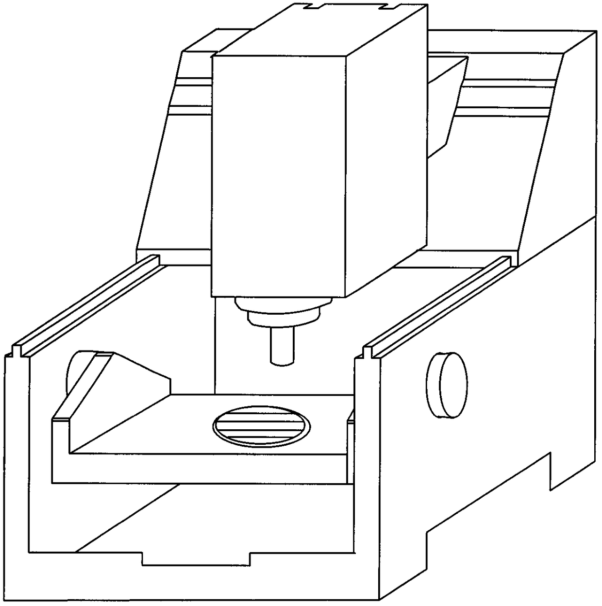
[0058] attached figure 1 Shown is a schematic structural diagram of a cradle-type five-axis CNC machine tool, and the method of the present invention is described by taking the machine tool as an example.

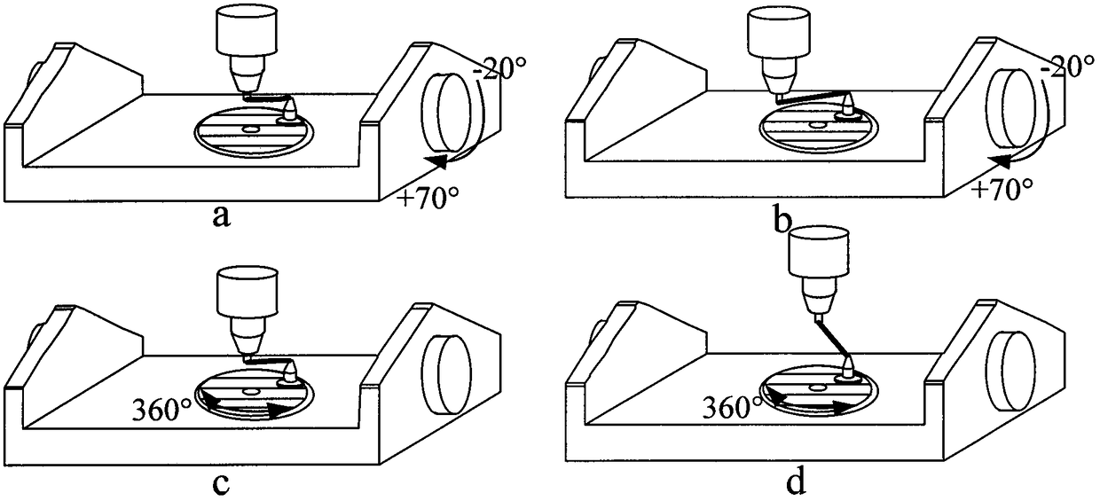
[0059] In step 1, according to the structure of the machine tool and the position of the rotary axis, the installation position of the ballbar is determined, and then the position-independent geometric error of the rotary axis is independently detected, including steps:

[0060] Step 1.1. The two rotary axes (A axis and C axis) are detected in four steps. According to the structure of the machine tool and the positions of the A-axis and the C-axis, the spindle tool cup of the ballbar is installed on the center of rotation of the A-axis; the base of the ballbar is installed on the turntable of the C-axis, and the distance from the center of ro...


PUM


Abstract

The invention discloses a multi-spindle machine tool geometric error identification method based on ball bar measurement. The method comprises the following steps of determining the mounting positionof a ball bar according to the structure of a machine tool and the position of a rotation shaft, and then independently detecting position-independent geometric errors of the rotation shaft; identifying position-independent geometric errors of a linear shaft in a mode of combination of the linear shaft and the rotation shaft; and obtaining the relation between the coordinates of the linear shaft and the angle position of the rotation shaft in combination of a specific detection track, establishing a position-independent geometric error identifying matrix of the rotation shaft and the linear shaft through a homogeneous change matrix, and then decoupling each position-independent geometric error. The position-independent geometric errors of the five-spindle machine tool are identified through comparison of experiment results and a simulation result. Detection equipment only needs to be installed once during the detection steps, measurement is convenient, and the identifying precision ishigh.

Description

technical field [0001] The invention relates to the field of precision detection of multi-axis numerically controlled machine tools, in particular to a method for identifying geometric errors of multi-axis machine tools based on ballbar measurement. technical background [0002] With the increasing proportion of five-axis machine tools in the manufacturing industry, the demand for machine tool accuracy testing is also gradually increasing. For the accuracy detection of multi-axis machine tools, devices such as ballbar, laser interferometer and R-test have appeared. Among them, due to the advantages of low cost, short detection time, and simple detection procedures, the ballbar is regarded as an ideal tool for precision detection. [0003] At present, there are relatively few identification methods involving geometric errors of both linear axes and rotary axes that are independent of position, and most of the identification accuracy is not high, and the installation of exper...

Claims


Application Information

Patent Timeline
Patent Type & Authority Applications(China)
IPC IPC(8): B23Q17/00
CPCB23Q17/00
Inventor 蒋晓耕姚思涵
Owner TIANJIN POLYTECHNIC UNIV
Why Eureka
Try Eureka