Steel template grinding machine

A steel formwork and grinding machine technology, which is applied in the direction of grinding frame, grinding machine parts, grinding machines, etc., can solve the problem that the bristles of the steel formwork are easy to wear, and achieve the effects of easy grinding, quick wetting, and slip prevention

Pending Publication Date: 2018-07-31
ANHUI UNIV OF SCI & TECH
0 Cites 0 Cited by

AI-Extracted Technical Summary

Problems solved by technology

[0002] In the construction process of high-rise buildings and large bridges, it is necessary to use steel formwork and bound steel cages together to pour concrete. Grind the blocks clean and put them back for the next use. Because the concrete agglomerates on the surface of the steel formwork are relatively hard, it is difficult to polish the concrete agglomerates at one time with the existing steel formwork grinder, and the concrete agglomerates will be damaged for a long time. Grinding will make the bristles of the steel formwork very easy to wear. During the grindin...

Abstract

The invention belongs to the technical field of building construction facilities, and particularly relates to a steel template grinding machine. The grinding machine comprises a vehicle body, the vehicle body is provided with a cavity with an opening in the lower side, a plurality of vehicle wheels are connected to the lower part of the vehicle body, a water collecting cover is arranged in the vehicle body and is provided with a cavity with an opening in the lower part, the edge of the opening in the lower part of the water collecting cover is connected to a rubber ring, an upper plate of thevehicle body is connected to an upper plate of the water collecting cover through a connecting part, the connecting part comprises a first rotating wheel, the first rotating wheel is connected to a connecting rod, through holes allowing the connecting rod to pass through are formed in the upper plate of the vehicle body and the upper plate of the water collecting cover separately, external threadsare arranged on the connecting rod, and internal threads matched with the external threads on the connecting rod are arranged in the through hole of the upper plate of the vehicle body. The grindingmachine has the advantages of being high in grinding speed, good in grinding effect, safe and convenient to use.

Application Domain

Grinding carriagesGrinding machines +2

Technology Topic

Rubber ringBuilding construction +1

Image

  • Steel template grinding machine
  • Steel template grinding machine
  • Steel template grinding machine

Examples

  • Experimental program(1)

Example Embodiment

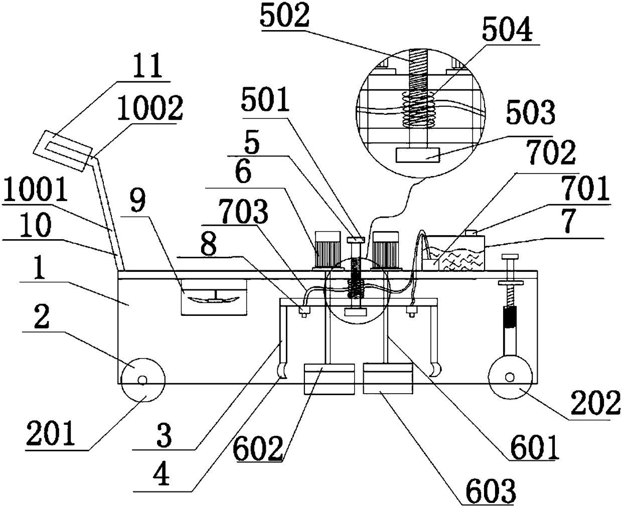
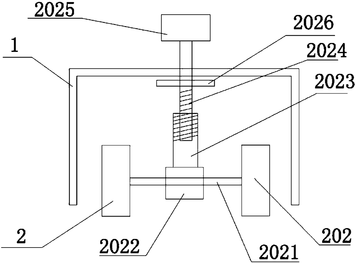
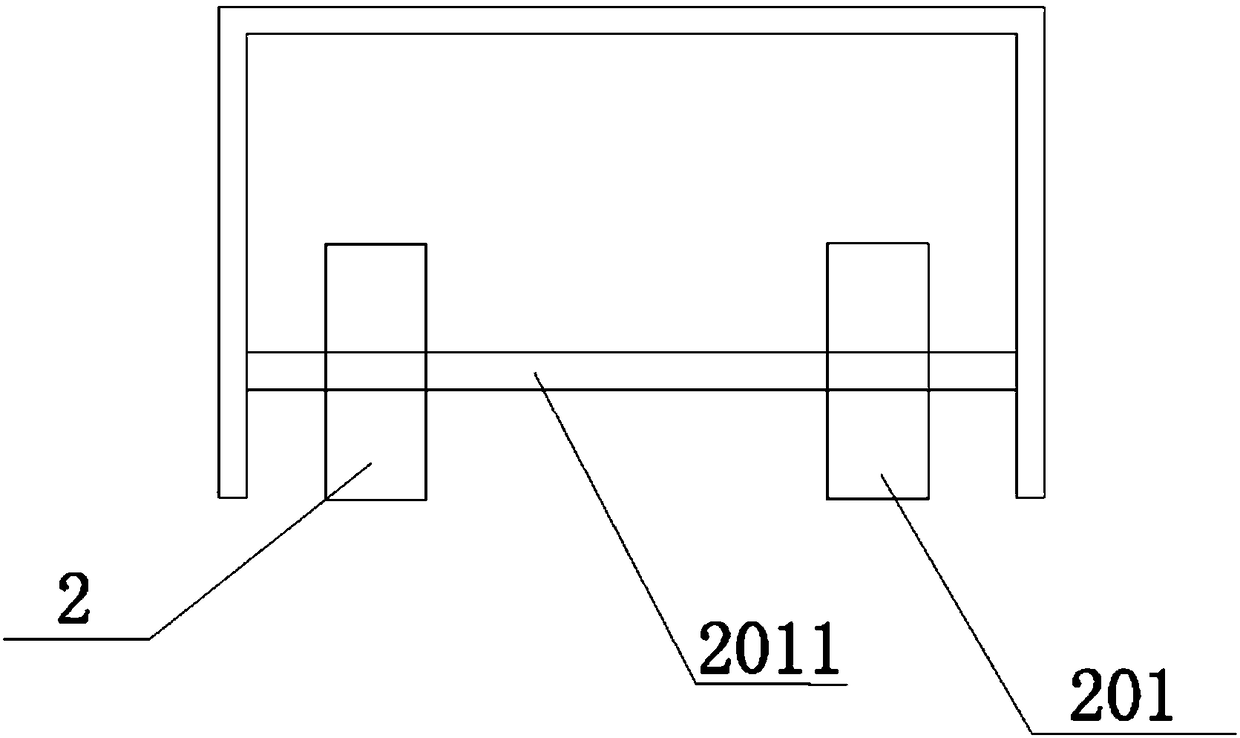
[0018] Such as Figure 1-4 As shown, a steel template grinding machine includes a car body 1, the car body 1 is a cavity with an opening on the lower side, four wheels 2 are connected below the car body 1, and a water collecting cover 3 is provided in the car body 1 The water collecting cover 3 is a cavity with a lower opening, the lower opening edge of the water collecting cover 3 is connected to the rubber ring 4, and the upper plate of the car body 1 and the upper plate of the water collecting cover 3 are connected by a connecting piece 5. The connecting piece 5 includes a A runner 501. The first runner 501 is connected to a connecting rod 502. The upper plate of the vehicle body 1 and the upper plate of the water collecting cover 3 are provided with through holes for the connecting rod 502 to pass through, and the connecting rod 502 is provided with external threads, The through hole of the upper plate of the car body 1 is provided with an internal thread that is used in conjunction with the external thread on the connecting rod 502. The connecting rod 502 penetrates the upper plate of the car body 1 and the upper plate of the water collecting cover 3 from top to bottom. The first partition plate 503 forms a structure in which the first runner 501 is located above the upper plate of the vehicle body 1, and the first partition plate 503 is located below the upper plate of the water collecting cover 3. The connecting rod 502 is sheathed with a spring 504, the spring 504 Located between the upper plate of the car body 1 and the upper plate of the water collecting cover 3, there are two rotating motors 6 on the upper end surface of the car body 1. The rotating motors 6 are connected to the turntable 602 through a rotating shaft 601, and the rotating shaft 601 is from the top The lower part penetrates the upper plate of the vehicle body 1 and the upper plate of the water collecting cover 3, the lower end surface of the turntable 602 is covered with bristles 603, the upper end surface of the vehicle body 1 is also provided with a water tank 7, and a water inlet 701 is provided above the water tank 7 The water tank 7 is provided with a water pump 702, and the lower end of the upper plate of the water collecting cover 3 is also provided with two sprinkler heads 8. The water pump 702 is connected to the sprinkler head 8 through a pipe 703, and the four wheels are 2 points Is the first wheel group 201 and the second wheel group 202. The first wheel group 201 includes two wheels 2 and a first rotating rod 2011. The first rotating rod 2011 penetrates the rotating shafts of the two wheels 2 of the first wheel group 201 and Both ends of the first rotating rod 2011 are connected to the side wall of the vehicle body 1, the second wheel set 202 includes two wheels 2 and a second rotating rod 2021, and both ends of the second rotating rod 2021 are respectively fixedly connected to the second wheel set 202 For the rotating shafts of the two wheels 2, the middle section of the second rotating rod 2021 is also sleeved with a bearing 2022, a sleeve 2023 is fixed on the bearing 2022, a sleeve rod 2024 is sleeved in the sleeve 2023, and an internal thread is provided in the sleeve 2023. The rod 2024 is provided with an external thread for use with the internal thread of the pipe sleeve 2023. The upper end of the sleeve rod 2024 penetrates the upper plate of the car body 1 and extends above the car body 1, and the upper end of the sleeve rod 2024 is provided with a second runner 2025 , The upper part of the sleeve rod 2024 is also fixedly sleeved with a second partition plate 2026. The second partition plate 2026 is located below the upper plate of the vehicle body 1. When the upper plate of the vehicle body 1 is parallel to the surface of the steel template, the brush 603 is in contact with the surface of the steel template plate. The lower end of the upper plate of the vehicle body 1 is provided with a blower 9, which is located between the first wheel set 201 and the water collecting cover 3. The vehicle body 1 is a rectangular parallelepiped cavity. , The water collecting cover 3 is a cylindrical cavity, and the rubber ring 4 is a ring formed by a rubber band The radius of the rubber ring 4 is the same as the radius of the water collecting cover 3 and the edge of the upper opening of the rubber ring 4 is fixedly connected with the edge of the lower opening of the water collecting cover 3. The upper end surface of the vehicle body 1 is also Two push rods 10 are connected. The two push rods 10 are parallel in the same plane. The push rod 10 includes a first inclined rod 1001 and a second inclined rod 1002. One end of the first inclined rod 1001 is connected to the upper end surface of the vehicle body 1. The other end of the first oblique rod 1001 is connected to one end of the second oblique rod 1002, the other end of the second oblique rod 1002 protrudes out of the car body 1, and the second oblique rod 1002 protrudes out of the end fixing sleeve of the car body 1. Set up non-slip sleeve 11.
[0019] When in use, first turn the second runner 2025, the second runner 2025 drives the sleeve rod 2024 to rotate, the sleeve rod 2024 moves upward, the second partition plate 2026 contacts the upper plate of the car body 1, and continues to rotate the sleeve rod 2024. The baffle plate 2026 lifts the upper plate of the water collecting cover 3 upwards, the position of the car body 1 above the first wheel set 201 is lifted upwards, the bristles 603 rise upwards to separate from the plate surface of the steel template. Hold the non-slip sleeve 11 and move the car body 1 above the dry concrete agglomerates on the steel template. During the movement, the bristles 603 are not in contact with the plate surface of the steel template to prevent the bristles 603 from being worn and moved during the movement. Then, align the bristles 603 with the concrete agglomerates that need to be polished, turn the second runner 2025, the car body 1 moves down, and the bristles 603 are in close contact with the concrete agglomerates, and then rotate the first runner 501 and the first runner 501 Rotate downwards, the first partition plate 503 will move downwards accordingly, and the spring 504 will press the water collecting cover 3 downwards. When the water collecting cover 3 is squeezed against the surface of the steel template, the water pump 702 is turned on and the water spray head 8 moves towards the The cleaning liquid is sprayed into the water cover 3, the switch of the rotating motor 6 is turned on, and the bristles 603 begin to polish the concrete agglomerates. Since the water collecting cover 3 is tightly pressed against the surface of the steel template, the cleaning liquid of the water collecting cover 3 is sprayed Gathered in the water trap 3, when the concrete agglomerates are polished, the cleaning fluid will continue to enter the concrete agglomeration from the surface of the concrete along with the polishing process, so that the inside of the concrete agglomeration is wetted, and the concrete agglomeration can be quickly carried out. After polishing, turn the first runner 501, the first runner 501 moves upwards, the first baffle plate 503 pulls up the water collecting cover 3, turn on the blower 9, and the blower 9 will be removed from the water collecting cover 3. The blown out blows out the surface of the steel template to prevent the grinding machine from slipping during movement. At the same time, rotate the second runner 2025, the second runner 2025 rotates upward, and the second runner 2025 drives the side of the car body 1 to lift. The bristles 603 are not in contact with the surface of the steel formwork, and the push rod 10 is pushed to move the steel formwork to another concrete agglomeration area that needs to be polished.

PUM

no PUM

Description & Claims & Application Information

We can also present the details of the Description, Claims and Application information to help users get a comprehensive understanding of the technical details of the patent, such as background art, summary of invention, brief description of drawings, description of embodiments, and other original content. On the other hand, users can also determine the specific scope of protection of the technology through the list of claims; as well as understand the changes in the life cycle of the technology with the presentation of the patent timeline. Login to view more.

Similar technology patents

Mirror polishing process of nitrogen spring piston rod

InactiveCN108747604Areduce scratchesEasy to polish
Owner:合肥济春机电科技有限公司

Automobile part grinding tool

InactiveCN109382722AImprove vacuuming effectEasy to polish
Owner:重庆精高金属结构制造有限公司

Handheld automatic dust collection wall surface polishing device

InactiveCN112157508AEasy to polish
Owner:JIANGSHAN FARUI DOORS & WINDOWS CO LTD

High-efficiency processing grinding tool for precision part

InactiveCN110877258AEasy to polish
Owner:树熊新材料科技(河源)股份有限公司

Classification and recommendation of technical efficacy words

  • Easy to polish

Grinding device for precise part machining

InactiveCN109108777AEasy to polishGood grinding effect
Owner:温惠青

Plate polishing device for machining

InactiveCN109531348AImprove cleanlinessEasy to polish
Owner:张彪

Polishing device for automobile accessory

PendingCN106926078AEasy to polishWide range of grinding
Owner:四川瑞丰锻造有限公司

Fixing mould clamp

InactiveCN108908109AWide range of useEasy to polish
Owner:廖像达

Automatic walnut sheller and shelling process

PendingCN112790396AImprove integrityEasy to polish
Owner:HEBEI YANGYUAN ZHIHUI BEVERAGE
Why Eureka
Try Eureka