Split type pier column anti-impact structure and installation method

An installation method and split-type technology, applied to road safety devices, roads, roads, etc., can solve the problems of occupying too many road resources, inconvenient installation, and high price, so as to reduce traffic jams, improve reliability, and reduce injuries Effect

Active Publication Date: 2018-07-31
SHENZHEN MUNICIPAL DESIGN & RES INST
View PDF9 Cites 0 Cited by
  • Summary
  • Abstract
  • Description
  • Claims
  • Application Information

AI Technical Summary

Problems solved by technology

However, the existing bridge pier column anti-collision facilities and research are mostly used in bridge piers in waterways and rivers. Due to factors such as ship shape, impact force, water area, etc., the bridge pier column anti-collision facilities in the river channel have large size, complex structure, inconvenient installation, and high price. Expensive etc.
The impact trajectory and impact force of ships and vehicles are quite different. At the same time, large-scale anti-collision structures cannot occupy too much road resources for pier columns. Therefore, it is urgent to develop anti-collision structures suitable for urban pier columns.

Method used


Image

  • Split type pier column anti-impact structure and installation method
  • Split type pier column anti-impact structure and installation method
  • Split type pier column anti-impact structure and installation method

Examples


Embodiment 1

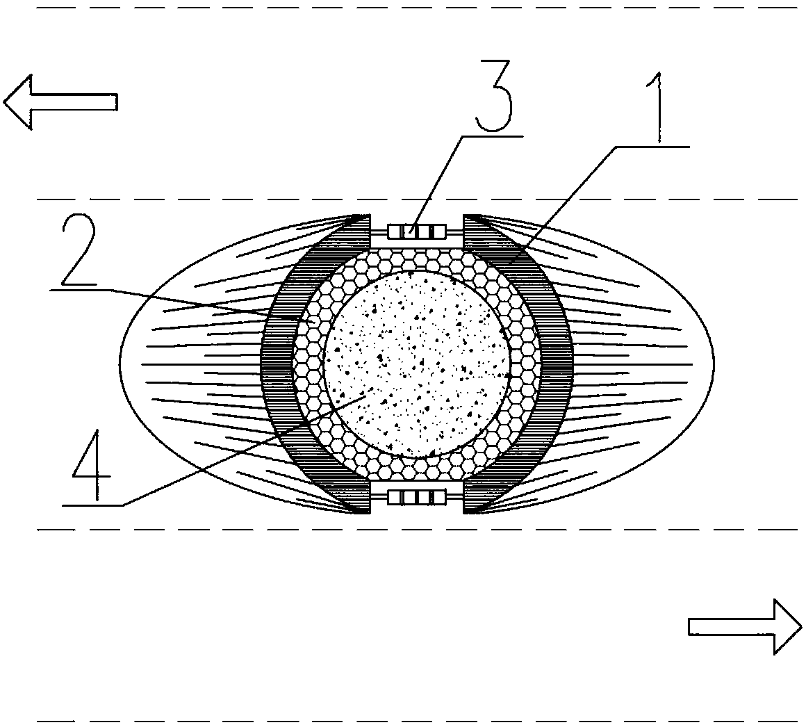
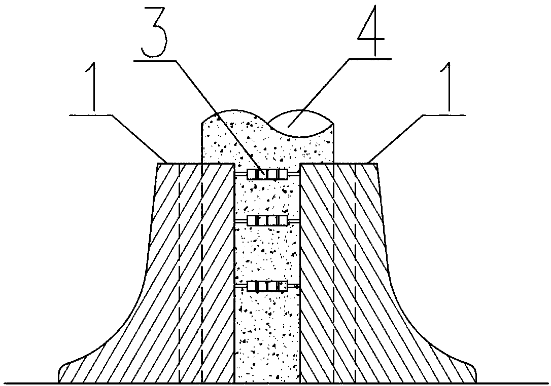
[0027] Such as Figure 1-2 As shown, this embodiment provides a split pier anti-collision structure, including two anti-collision structural boots 1 symmetrically arranged on the outside of the pier column, the two anti-collision structural boots 1 are separately arranged, and the anti-collision structural boots 1 pass through several A speed-locking damper 3 is connected, and a buffer layer 4 is filled between the anti-collision structural boot 1 and the pier column, and the cross-section of the anti-collision structural boot 1 increases sequentially from top to bottom. in, figure 1 The direction of the middle arrow is the driving direction on both sides of the pier.

[0028] In this specific embodiment, the piers are circular piers 4 . The arrangement density of the speed lock dampers 3 decreases sequentially from top to bottom, and the speed lock dampers 3 are arranged symmetrically with respect to the piers.

[0029] The anti-collision structural boots 1 are prefabricat...

Embodiment 2

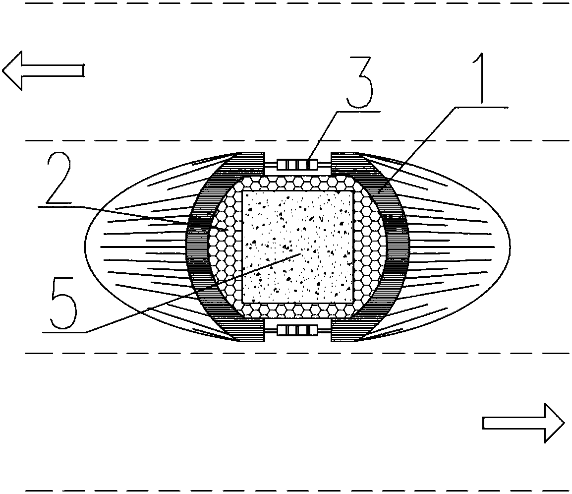
[0036] Such as Figure 3-4 As shown, the pier column in this embodiment is a rectangular pier column 5, and the other parts are the same as those in the first embodiment.


PUM


Abstract

The invention discloses a split type pier column anti-impact structure and an installation method and relates to the technical field of structural engineering. The split type pier column anti-impact structure comprises two separate anti-impact structural boots symmetrically arranged on the outer side of a pier column, the anti-impact structural boots are connected through speed locking dampers, the position between each anti-impact structural boot and the pier column is filled with a buffering layer, and the cross section of each anti-impact structural boot is gradually increased from top to bottom. The installation method of the split type pier column anti-impact structure includes the steps that the anti-impact structural boots are arranged in the direction parallel to the traveling direction and fixed to the ground, the speed locking dampers are installed between the two anti-impact structural boots, and the position between the pier column and each anti-impact structural boot is filled with the buffering layer. By the adoption of the split type pier column anti-impact structure and the installation method, stress time is prolonged through a buffering material, impact force is reduced, meanwhile, the anti-impact structural boots guide a vehicle to change the direction, so that huge impact force is eliminated, the damage degree of the vehicle is reduced as much as possible, the size of the anti-impact structure is reduced, and the road space is saved.

Description

technical field [0001] The invention relates to the technical field of structural engineering, in particular to a split-type pier column anti-collision structure and an installation method. Background technique [0002] In cities, when vehicles pass through complex urban overpass bridges or building crossing pier columns, collisions with pier columns often occur, resulting in bridge damage, vehicle damage, death, large economic losses, and bad social impact. However, the existing bridge pier column anti-collision facilities and research are mostly used in bridge piers in waterways and rivers. Due to factors such as ship shape, impact force, water area, etc., the bridge pier column anti-collision facilities in the river channel have large size, complex structure, inconvenient installation, and high price. Expensive and so on. The impact trajectory and impact force of ships and vehicles are quite different. At the same time, large-scale anti-collision structures cannot occupy...

Claims


Application Information

Patent Timeline
Patent Type & Authority Applications(China)
IPC IPC(8): E01F15/14
CPCE01F15/141Y02A30/30
Inventor 代亮何晓晖郭明王梦雨
Owner SHENZHEN MUNICIPAL DESIGN & RES INST
Why Eureka
Try Eureka