Supercharge Your Innovation With Domain-Expert AI Agents!

Air conditioner indoor unit

A technology for air-conditioning indoor units and casings, which is applied in air-conditioning systems, space heating and ventilation, space heating and ventilation details, etc. It can solve the problems of air-conditioning indoor units such as reduced wind speed, stay at the theoretical level, and low air volume, and achieve expansion The effect of air supply range and air volume, increase of air supply speed, and air balance

Pending Publication Date: 2018-07-31
QINGDAO HAIER AIR CONDITIONER GENERAL CORP LTD
View PDF11 Cites 0 Cited by
  • Summary
  • Abstract
  • Description
  • Claims
  • Application Information

AI Technical Summary

Problems solved by technology

Although this kind of air-conditioning indoor unit can solve the above-mentioned problems of low air volume and large airflow pressure loss to a certain extent, the effect is not particularly obvious, and it cannot solve the problem of high noise at all.
Defects that users can experience intuitively, such as loud noise and low air volume, have seriously affected the overall performance of the indoor unit of the air conditioner, and greatly limited the scope of use of the indoor unit of the air conditioner.
[0004] In order to reduce noise, the air-conditioning indoor units involved in some of the currently disclosed patent documents simply replace the fan with an ion wind device. However, the ion wind speed generated by the ion wind device is extremely limited, and the replaced air-conditioning indoor unit The wind speed is greatly reduced, which can hardly meet the most basic needs of users
It is precisely because there are many defects and impracticalities in the existing technical solutions, so far, the technology of using ion wind to supply air has only stayed at the most basic theoretical level

Method used


Image

  • Air conditioner indoor unit
  • Air conditioner indoor unit
  • Air conditioner indoor unit

Examples


Embodiment Construction

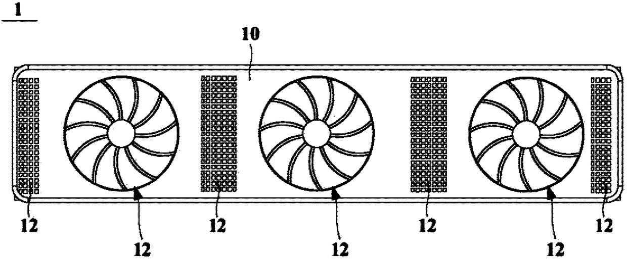
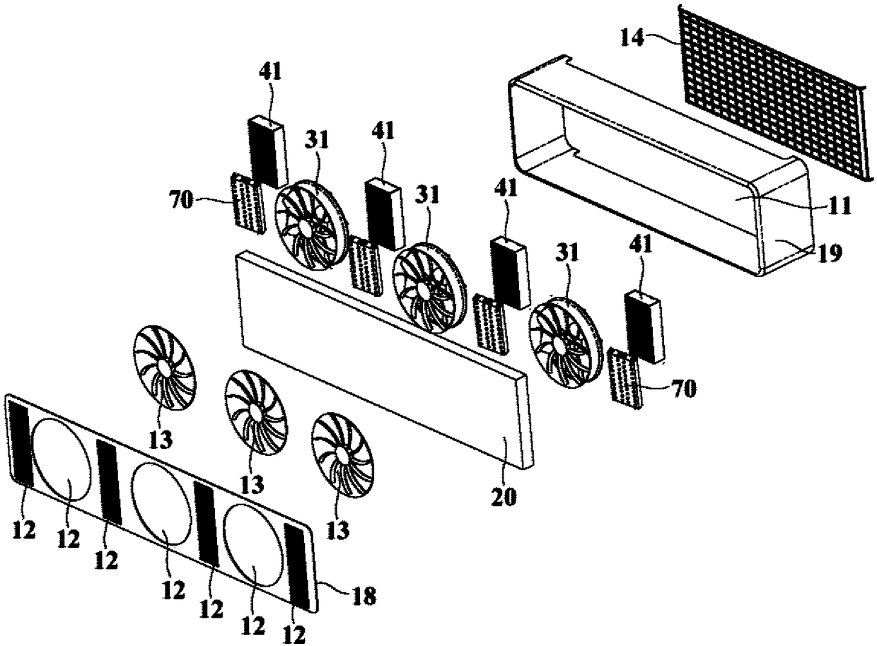
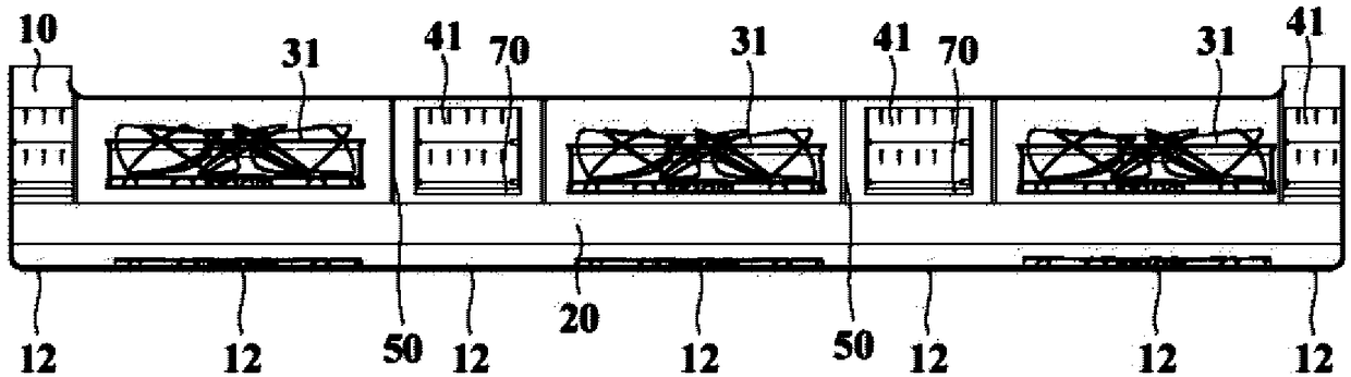
[0044] An embodiment of the present invention provides an air conditioner indoor unit, figure 1 is a schematic front view of an air conditioner indoor unit according to an embodiment of the present invention, figure 2 is a schematic exploded view of an air conditioner indoor unit according to an embodiment of the present invention, image 3 is a schematic sectional view of an air conditioner indoor unit according to an embodiment of the present invention. see Figure 1 to Figure 3 , the air conditioner indoor unit 1 of the embodiment of the present invention includes a casing 10 , a heat exchange device 20 , at least one first axial fan 31 and at least one first ion wind generating device 41 . exist Figure 1 to Figure 3 In the shown embodiment, the number of the first axial fans 31 is three, and the number of the first ion wind generators 41 is four. In other embodiments, the number of the first axial fan 31 can also be one, two or more than three, and the number of the ...


PUM


Abstract

The invention relates to an air conditioner indoor unit. The air conditioner indoor unit comprises a machine shell, a heat exchange device, at least one axial flow draught fan and at least one first ionic wind generation device. The machine shell is provided with at least one air inlet allowing environment air to enter and at least one air outlet allowing an inner air flow to flow out, the at least one air outlet is formed in the front side of the machine shell, the heat exchange device is arranged in the machine shell and is arranged to exchange heat with at least part of air flow entering the machine shell through the at least one air inlet, and the at least one axial flow draught fan and theat least one first ionic wind generation device are controlled to promote the air flow in the machine shell to flow towards theat least one air outlet, and are arranged at the air flow flowing path, from the at least one air inlet to the at least one air outlet, in the machine shell in a parallelconnection manner. The air conditioner indoor unit is large in air supply range and air supply amount, small in noise and balanced in air flow.

Description

technical field [0001] The invention relates to air-conditioning technology, in particular to an air-conditioning indoor unit. Background technique [0002] At present, most of the traditional wall-mounted air conditioner indoor units adopt the airflow circulation mode of upper air intake and lower air outlet, and the devices used to drive the air circulation are mostly cross-flow fans. The airflow enters the interior of the cross-flow fan along the axial direction perpendicular to the cross-flow fan, and passes through the impeller of the cross-flow fan twice. Inside the impeller, the airflow is forced to bend, which makes the pressure loss of the airflow larger and the air volume lower , the noise is louder when the whole machine is running. [0003] In order to avoid a series of problems caused by using a cross-flow fan to drive air circulation, some air-conditioning indoor units in the prior art replace the cross-flow fan with a centrifugal fan or an axial-flow fan. Al...

Claims


Application Information

Patent Timeline
Patent Type & Authority Applications(China)
IPC IPC(8): F24F1/00F24F13/20F24F13/30F24F13/00A61L9/22F24F13/08F24F13/24
CPCA61L9/22F24F1/0029F24F1/0033F24F1/0057F24F13/00F24F13/08F24F13/20F24F13/24F24F13/30F24F2013/247
Inventor 李健王永涛
Owner QINGDAO HAIER AIR CONDITIONER GENERAL CORP LTD
Features
  • R&D
  • Intellectual Property
  • Life Sciences
  • Materials
  • Tech Scout
  • Unparalleled Data Quality
  • Higher Quality Content
  • 60% Fewer Hallucinations
Learn More