Air conditioner system

A technology of air conditioning system and flow regulating device, which is applied in air conditioning system, space heating and ventilation, heating mode, etc., can solve the problems of short circuit, condensation water dripping, condensation in cooling pipelines, etc., to avoid condensation, The effect of simplifying control and avoiding condensation on cooling pipes

Inactive Publication Date: 2018-07-31
DAIKIN IND LTD
View PDF6 Cites 3 Cited by
  • Summary
  • Abstract
  • Description
  • Claims
  • Application Information

AI Technical Summary

Problems solved by technology

[0004] However, in the above-mentioned air conditioning system, the temperature of the refrigerant flowing into the cooling pipe from the inlet side may be lower than the dew point temperature of the air, so dew condensation may occur on the cooling pipe (especially on the inlet side). In this case, dew condensation water may drip onto the electrical components constituting the air-conditioning system and cause problems such as short circuits, which is not ideal.

Method used


Image

  • Air conditioner system
  • Air conditioner system

Examples


Embodiment approach 1

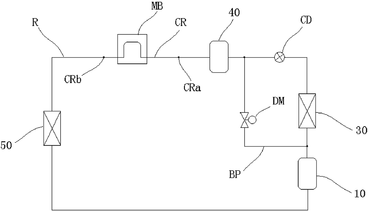
[0039] The air conditioning system according to Embodiment 1 of the present invention will be described below with reference to the drawings, wherein, figure 1 It is a schematic diagram showing the circuit configuration of the air conditioning system according to Embodiment 1 of the present invention.

[0040] Such as figure 1 As shown, the air conditioning system includes a compressor 10, an outdoor heat exchanger 30, an outdoor flow regulating device CD, a storage tank 40 and an indoor heat exchanger 50 connected in sequence by a refrigerant pipeline R, and the storage tank 40 is connected to the indoor heat exchanger 50. The refrigerant line R between the heat exchangers 50 includes a cooling line CR having an inlet port CRa and an outlet port CRb.

[0041] Here, the cooling pipe CR is in contact with the electrical components via the metal plate MB.

[0042] In addition, the air conditioning system also includes a storage tank pressurization pipeline BP and a control uni...

Embodiment approach 2

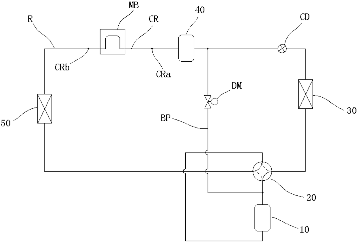
[0060] Refer below figure 2 , the air conditioning system according to Embodiment 2 of the present invention will be described, wherein, figure 2 It is a schematic diagram showing the circuit configuration of the air conditioning system according to Embodiment 2 of the present invention.

[0061] The configuration of the air-conditioning system of this embodiment is basically the same as that of the air-conditioning system of Embodiment 1 described above, except that a switching device 20 is provided in the air-conditioning system of this embodiment.

[0062] Specifically, as figure 2 As shown, a switching device 20 for switching the air conditioning system between cooling operation and heating operation is provided on the refrigerant pipeline CR between the compressor 10 and the outdoor heat exchanger 30, and the accumulator pressurization pipeline BP One end is connected between the compressor 10 and the switching device 20, and the other end is connected between the st...


PUM


Abstract

The invention discloses an air conditioner system which contributes to avoiding moisture condensation of a cooling pipeline forming one part of a refrigerant pipeline. The air conditioner system comprises a compressor, an outdoor heat exchanger, an outdoor flow adjusting device, a storage tank and an indoor heat exchanger which are sequentially connected through the refrigerant pipeline. The portion, between the storage tank and the indoor heat exchanger, of the refrigerant pipeline comprises the cooling pipeline. The air conditioner system further comprises a storage tank pressurization pipeline provided with a flow control element and a control portion which controls operation of the air conditioner system. One end of the storage tank pressurization pipeline is connected to the portion between the compressor and the outdoor heat exchanger, the other end of the storage tank pressurization pipeline is connected to the portion between the storage tank and the outdoor flow adjusting device, and the opening of the flow control element is increased through the control portion when it is judged that moisture condensation conditions of the cooling pipeline are met.

Description

technical field [0001] The present invention relates to an air-conditioning system, in particular to an air-conditioning system which uses a cooling pipeline to cool electrical components. Background technique [0002] In the past, there was an air conditioning system, which included a compressor, an outdoor heat exchanger, an outdoor flow regulator, a storage tank, and an indoor heat exchanger connected in sequence by a refrigerant pipeline, and the refrigerant between the storage tank and the indoor heat exchanger The pipeline includes a cooling pipeline having an inlet port and an outlet port, and the cooling pipeline is in contact with the electrical component through the metal plate. [0003] In the above air conditioning system, the electrical components can be cooled by the refrigerant that flows through the cooling pipeline due to the heat exchange with the air in the outdoor heat exchanger and the temperature is lowered. Compared with cooling, the structure can be ...

Claims


Application Information

Patent Timeline
Patent Type & Authority Applications(China)
IPC IPC(8): F24F5/00F24F11/41F25B47/00F25B13/00
CPCF24F5/001F25B13/00F25B47/00F24F5/00F24F11/41F25B1/00
Inventor 冈本敦
Owner DAIKIN IND LTD
Why Eureka
Try Eureka