
Wall-mounted solar hot water system

A technology for solar water heating and solar thermal collectors, which is applied to the field of wall-mounted solar water heating systems, can solve the problems of not being able to recycle the heat of gas stoves, and that solar thermal collectors cannot be hung on the wall and installed, etc. Good effect, convenient maintenance and good economy effect

Inactive Publication Date: 2018-07-31
浙江英科新能源有限公司
View PDF6 Cites 0 Cited by
  • Summary
  • Abstract
  • Description
  • Claims
  • Application Information

AI Technical Summary

Problems solved by technology

[0004] The first object of the present invention is to provide a wall-mounted solar water heating system in which the solar collector can be installed on the wall, which solves the problem that the solar collector of the existing solar water heater cannot be hung on the wall for installation
[0005] The second purpose of the present invention is to further provide a wall-mounted solar water heating system that can recycle the heat released by the gas stove and the sun, which solves the problem that the existing solar water heaters cannot recycle the heat released by the gas stove. heat problem

Method used


Image

  • Wall-mounted solar hot water system
  • Wall-mounted solar hot water system
  • Wall-mounted solar hot water system

Examples


Embodiment 1

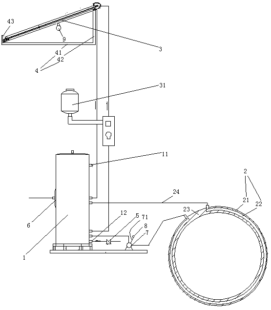
[0032] Embodiment one, see figure 1 , a wall-mounted solar water heating system, including a water tank 1, a gas stove heat recovery device 2, a solar collector 3 and a hanging mounting frame 4.

[0033] The water tank 1 is also provided with a hot water outlet 11 and a cold water inlet 12 . A one-way valve 5 is installed in the cold water inlet 12 . The one-way valve 5 is opened toward the inside of the water tank 1 . An electric heater 6 is also provided in the water tank 1 . The electric heater 6 is used for heating the water in the water tank 1 .

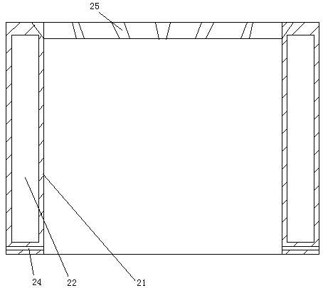
[0034] The gas stove heat recovery device 2 includes a heat insulating cylinder 21 and a water ring 22 arranged in the wall of the heat insulating cylinder and extending along the circumferential direction of the heat insulating cylinder. The water ring 22 is an open structure. Both ends of the opening 23 of the water ring are communicated with the water tank 1 through the water pipe 24 . The water pipe 24 is connected wit...

Embodiment 2

[0046] Embodiment two, the difference with embodiment one is:

[0047] see Figure 5 , also includes the resistance speaker 97.

[0048] The damping ring 96 is provided with an axial support surface 961 and a radial support surface 962 . The damping ring 96 is only connected together with the supporting sheet and the connecting ring by abutting.

[0049] The resistance box 97 includes a box body 971 and a box cover 972 . The box body 971 is circular. The box body 971 is composed of an upper round tube section 9711 and a lower round tube section 9712 . The diameter of the upper round pipe section 9711 is greater than the diameter of the lower round pipe section 9712 . A sealing step 973 is formed between the upper round pipe section 9711 and the lower round pipe section 9712 . The sealing step 973 is in sealing contact with the axial supporting surface 961 . The peripheral surface of the upper circular pipe section 9711 is in sealing contact with the radial support surfa...


PUM


Abstract

The invention relates to a solar water heater. A wall-mounted solar hot water system comprises a water tank, a solar heat collector forming a circulating loop with the water tank and a hanging type mounting bracket. The solar heat collector is connected with an illuminating lamp. The hanging type mounting bracket comprises a horizontal bracket and a vertical bracket connected to one end of the horizontal bracket. A blocking frame is arranged at the other end of the horizontal bracket. One end of the solar heat collector is placed on the horizontal bracket and abuts against the blocking frame together. The other end of the solar heat collector is fixed to the upper end of the vertical frame. A bolt hole extending in the horizontal direction is formed in the vertical frame. The wall-mountedsolar hot water system with the solar water heater capable of being wall-mounted solves the problem that a solar heat collector of an existing solar water heater cannot be hung on the wall for installation.

Description

technical field [0001] The invention relates to a solar water heater, in particular to a wall-mounted solar water heating system. Background technique [0002] The solar water heater is a water heater heated by solar energy. When in use, the solar water heater only needs to be installed in a place where the sun can shine for a long time, and the cold water can be heated by the solar energy. Solar water heaters are widely used due to their low cost and no environmental pollution. [0003] Existing solar water heaters can only use solar energy to heat water or assist with electric heating, but cannot recover the heat emitted by gas stoves for heating water; solar collectors can only be placed on the roof It can be fixed on the wall, and cannot be fixed on the wall. Contents of the invention [0004] The first object of the present invention is to provide a wall-mounted solar water heating system in which the solar heat collector can be installed on the wall, which solves t...

Claims


Application Information

Patent Timeline
Patent Type & Authority Applications(China)
IPC IPC(8): F24S80/00F24S20/40F24S25/00F21V33/00
CPCY02E10/47F21V33/00
Inventor 吴忠南卢丽华
Owner 浙江英科新能源有限公司
Learn More