Angular Velocity Measuring Device Based on Tunable Photoelectric Oscillator
What is Al technical title?
Al technical title is built by PatSnap Al team. It summarizes the technical point description of the patent document.
A technology of photoelectric oscillator and measuring device, which is applied in the field of optical gyroscope to achieve the effect of improving dynamic range, avoiding interference and improving sensitivity
Active Publication Date: 2020-08-25
BEIJING JIAOTONG UNIV
View PDF5 Cites 0 Cited by
Summary
Abstract
Description
Claims
Application Information
AI Technical Summary
This helps you quickly interpret patents by identifying the three key elements:
Problems solved by technology
Method used
Benefits of technology
Problems solved by technology
[0008] In addition, for the measurement system, high sensitivity and large dynamic range are generally contradictory. In actual use, you need to make a trade-off between sensitivity and dynamic range according to your own needs, which will bring a lot of inconvenience. Therefore, research Gyroscopes with high sensitivity and large dynamic range are of great significance
Method used
Image
Click on the blue label to locate the original text in one second.
Reading with bidirectional positioning of images and text.
Examples
Embodiment Construction
[0039] Embodiments of the present invention are described in detail below, examples of which are illustrated in the accompanying drawings, wherein the same or similar reference numerals refer to the same or similar elements or elements having the same or similar functions throughout. The embodiments described below by referring to the figures are exemplary only for explaining the present invention and should not be construed as limiting the present invention.
[0040] It will be understood by those skilled in the art that the singular forms "a", "an", "the" and "the" as used herein can include the plural forms as well, unless expressly stated otherwise. It should be further understood that the word "comprising" used in the description of the present invention refers to the presence of said features, integers, steps, operations, elements and or components, but does not exclude the presence or addition of one or more other features, Integers, steps, operations, elements, compone...
PUM
Abstract
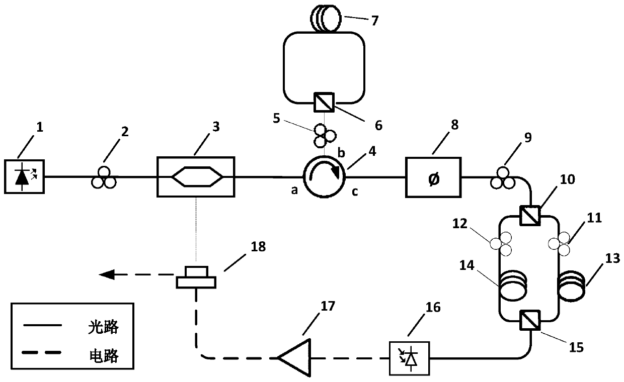
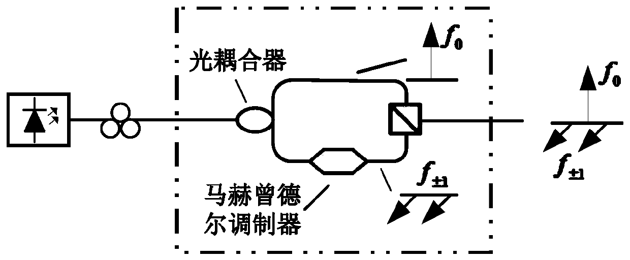
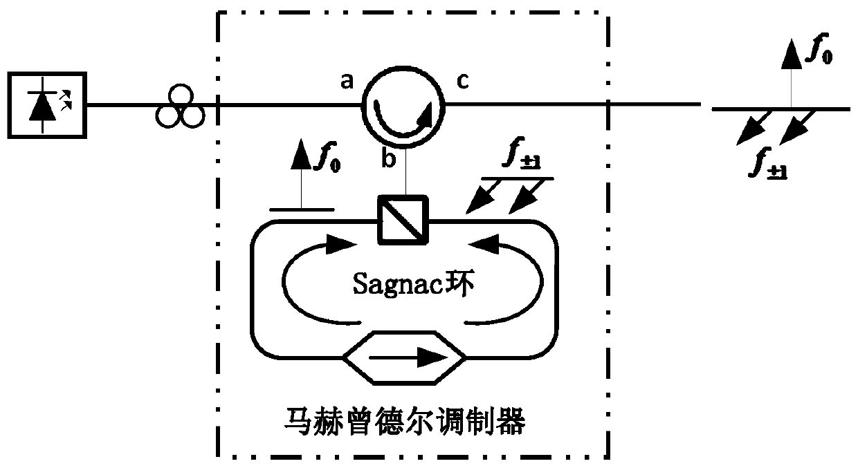
The invention provides an angular velocity measuring device based on a tunable optoelectronic oscillator. The angular velocity measuring device comprises a laser source, a first polarization controller, an electro-optic modulating element, an optical circulator, a second polarization controller, a first polarization beam splitter / combiner, a Sagnac ring, a dispersion element, a third polarizationcontroller, a second polarization beam splitter / combiner, a fourth polarization controller, a fifth polarization controller, a first segment of optical fiber, a second segment of optical fiber, a third polarization beam splitter / combiner, a photoelectric detector, a microwave amplifier, and a power divider. According to the angular velocity measuring device, the Sagnac interferometer is embedded into a microwave photonic filter, so that phase change caused by Sagnac effect is converted into the center frequency of the microwave photonic filter, and change of optoelectronic oscillator output microwave signal frequency is induced. The tunable range of the microwave photonic filter is usually at GHz scale, and the optoelectronic oscillator is capable of generating high quality microwave signals, so that the system is capable of increasing angular velocity measuring sensitivity, and widening the dynamic range at the same time.
Description
technical field [0001] The invention relates to the technical field of optical gyroscopes, in particular to an angular velocity measuring device based on a tunable photoelectric oscillator. Background technique [0002] As an important aspect of inertial technology, angular velocity measurement plays a huge role in the fields of military, industrial and civil navigation. The discovery of the Sagnac effect laid a theoretical foundation for the development of optical gyroscopes. The Sagnac effect points out that the two beams of light propagating forward and backward along the closed optical loop will produce a phase difference when the loop rotates, and the phase difference is proportional to the angular velocity of the loop rotation, the expression is [0003] [0004] Among them, A is the area of the closed optical loop; λ is the wavelength of the two beams of light; n is the refractive index of the medium that makes up the optical loop; c is the propagation speed of l...
Claims
Application Information
Patent Timeline
Application Date:The date an application was filed.
Publication Date:The date a patent or application was officially published.
First Publication Date:The earliest publication date of a patent with the same application number.
Issue Date:Publication date of the patent grant document.
PCT Entry Date:The Entry date of PCT National Phase.
Estimated Expiry Date:The statutory expiry date of a patent right according to the Patent Law, and it is the longest term of protection that the patent right can achieve without the termination of the patent right due to other reasons(Term extension factor has been taken into account ).
Invalid Date:Actual expiry date is based on effective date or publication date of legal transaction data of invalid patent.