
Sts multi-trolley portal gantry container crane

A gantry crane and portal type technology, which is applied in the direction of trolley cranes, cranes, hoisting devices, etc., can solve the problems of bulkiness, poor aerodynamic performance, expensive cranes, etc. effect of time

Active Publication Date: 2018-07-31
弗拉基米尔·内夫希马尔-卫登霍费尔
View PDF11 Cites 3 Cited by
  • Summary
  • Abstract
  • Description
  • Claims
  • Application Information

AI Technical Summary

Problems solved by technology

[0010] These cranes also have the disadvantage of having relatively poor aerodynamic performance which limits their ability to operate in high winds
The crane includes four pairs of legs for stabilization, and the crane is very expensive and heavy

Method used


Image

  • Sts multi-trolley portal gantry container crane
  • Sts multi-trolley portal gantry container crane
  • Sts multi-trolley portal gantry container crane

Examples


Embodiment Construction

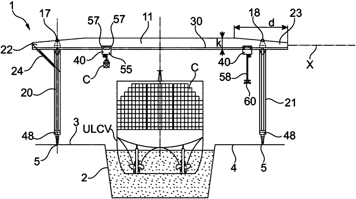
[0075] figure 1 A container terminal 1 according to the invention is shown. The pier 1 comprises a recessed berth 2 extending between opposing left pier 3 and right pier 4 . Preferably, Berth 2 is configured for receiving Ultra Large Container Vessels (ULCVs) as shown. Such ships typically carry over 13000 TEU.

[0076] The berth 2 may include lanes and / or rails and various facilities (not shown) for transporting and storing containers unloaded from ships or waiting to be unloaded.

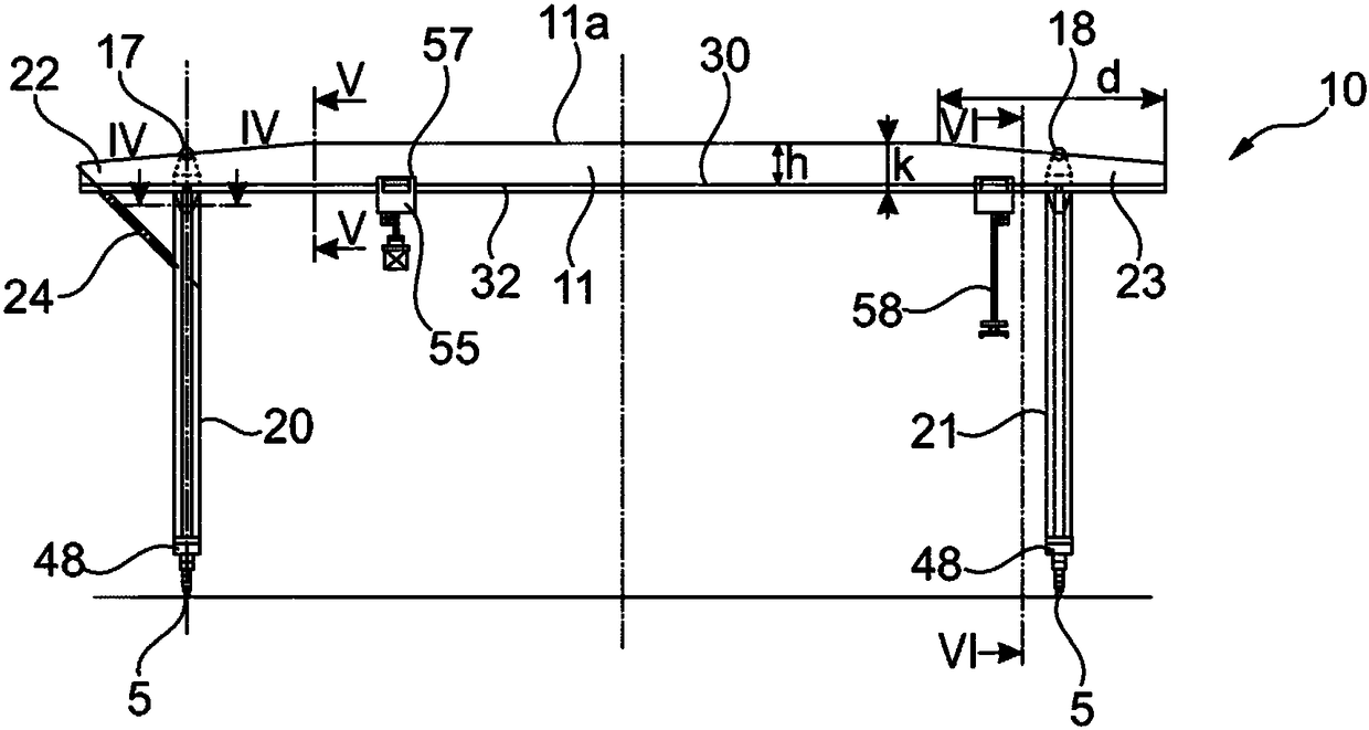
[0077] Two rails 5 extend along the berth 2 on both sides of the berth 2 for running at least one portal crane 10 made according to the invention. Preferably, there is more than one crane 10 on track 5 . There may be as many as four cranes 10 .

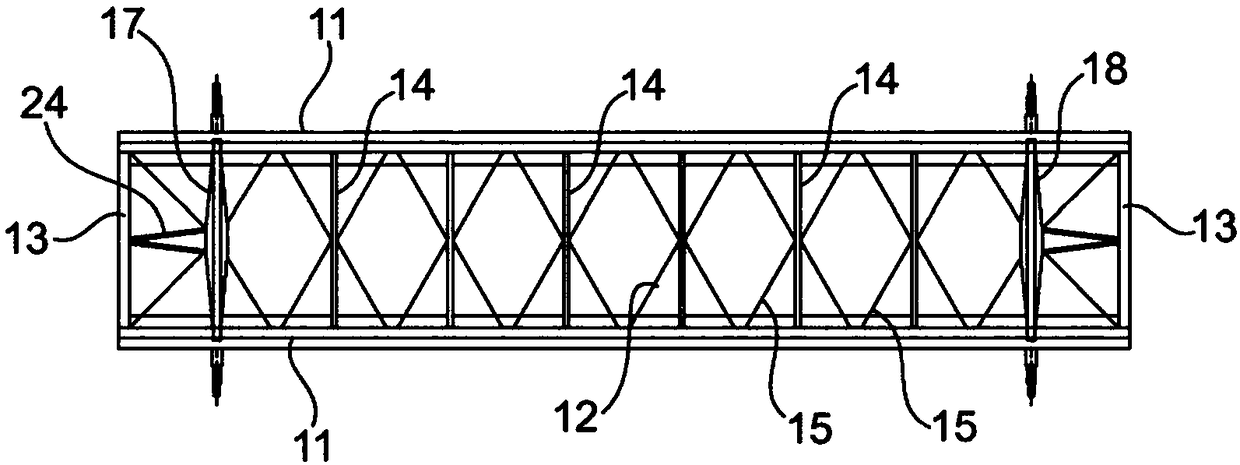
[0078] Such as image 3 As shown, each crane 10 comprises two parallel horizontal girders 11 . Two parallel horizontal main beams 11 are connected together by struts 12 which may include end beams 13 as shown, transverse intermediate beams 14 of s...


PUM


Abstract

Portal gantry crane comprising: two parallel main girders (11) running side by side on respective sides of a midplane (M), two legs (20, 21) each positioned in said midplane (M), two couples of trolleys (40), each couple of trolleys operating on a corresponding girder (11), each trolley carrying a hoist.

Description

technical field [0001] The invention relates to a portal type gantry crane for loading / unloading containers on / off ships. Background technique [0002] Container cranes are widely used around the world to load / unload container ships at container terminals. [0003] In order to realize terminal functions in an economical and optimal way, it is necessary that the cranes have a high utilization rate. [0004] In a conventional container terminal, ships dock along the quay, and conventional Ship-to-Shore (STS) container cranes are used to load / unload the ships from one side. [0005] US 2003 / 0108405 A1 figure 2 A traditional quay crane is depicted. [0006] Typically, such cranes include a superstructure balanced by counterweights that move along the berth on two parallel tracks. The beams cantilever over the quay line and to the rear of the superstructure. The ropes connect the main beams to the vertices of the superstructure. This traditional crane is also known as a Pan...

Claims


Application Information

Patent Timeline
Patent Type & Authority Applications(China)
IPC IPC(8): B66C19/00B66C5/02
CPCB66C5/02B66C19/00B66C13/08B66C19/007B66C13/18B66C19/002B66C2700/01B66C2700/0328
Inventor 弗拉基米尔·内夫希马尔-卫登霍费尔
Owner 弗拉基米尔·内夫希马尔-卫登霍费尔
Learn More