
Depth mapping with a head mounted display using stereo cameras and structured light

A structured light and structured light lighting technology, applied in stereo systems, stereo photography, instruments, etc., can solve problems such as performance degradation, SL solution degradation, and small background brightness.

Pending Publication Date: 2018-07-31
CTRL LABS CORP
View PDF11 Cites 3 Cited by
  • Summary
  • Abstract
  • Description
  • Claims
  • Application Information

AI Technical Summary

Problems solved by technology

However, measurements of SL designs are affected by having an in-band background light level in the local area being imaged
For example, in cases where the brightness of the ambient light in a localized area spans multiple levels of magnitude (equal to or brighter than the apparent intensity of the SL source), the SL scheme degrades (since the signal of interest eventually disappears in the background light source in the photon noise limit of
Time-of-Flight (ToF) architectures experience similar performance degradation at increasing ambient brightness
However, stereo vision cannot capture 3D scene information without at least minimal background luminance via controlled or uncontrolled environmental sources

Method used


Image

  • Depth mapping with a head mounted display using stereo cameras and structured light
  • Depth mapping with a head mounted display using stereo cameras and structured light
  • Depth mapping with a head mounted display using stereo cameras and structured light

Examples


Embodiment Construction

[0016] System Overview

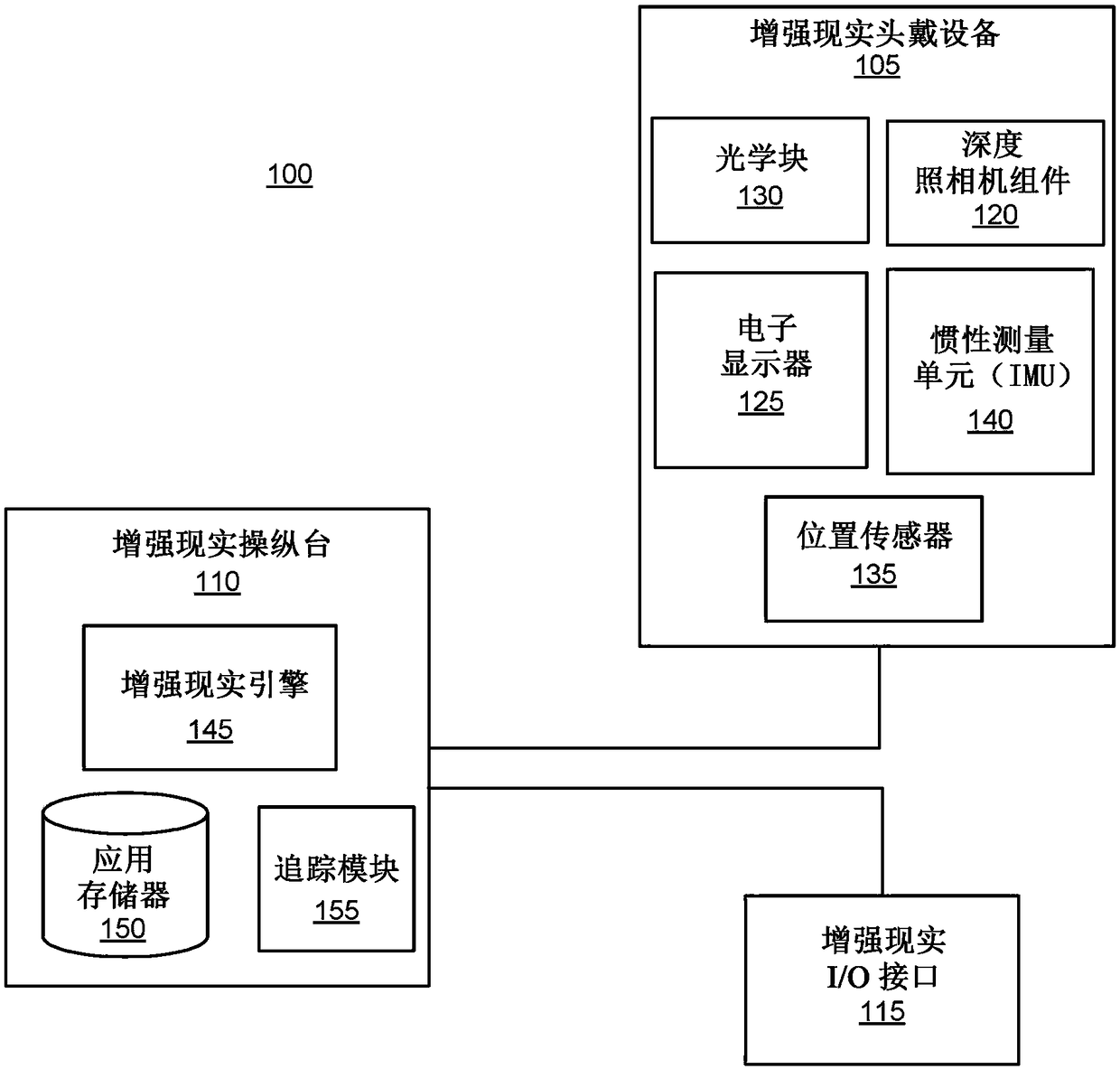
[0017] figure 1 is a block diagram of one embodiment of an augmented reality (AR) system environment 100 in which an AR console 110 operates. As used herein, the AR system environment 100 may also include a virtual reality system environment that presents a user with a virtual environment with which the user can interact. pass figure 1 The illustrated AR system environment 100 includes an AR headset 105 and an AR input / output (I / O) interface 115 each coupled to an AR console 110 . Although figure 1 An example of system 100 including one AR headset 105 and one AR I / O interface 115 is shown, in other embodiments any number of these components may be included in AR system environment 100 . For example, there may be multiple AR headsets 105 , each having an associated AR I / O interface 115 with which each AR headset 105 communicates with the AR console 110 . In alternative configurations, different and / or additional components may be included in the AR...


PUM


Abstract

A an augmented reality (AR) headset includes a depth camera assembly that combines stereo imaging with structured light (SL) to generate depth information for an area of interest. The depth camera assembly includes at least two image capture devices and a SL illuminator and determines an imaging mode based on a signal to noise ratio or spatial variance of images captured by one or more of the cameras. Different imaging modes correspond to different operation of one or more image capture devices and the SL illuminator. The depth camera assembly includes different ranges of signal to noise ratios that each correspond to an imaging mode, and the depth camera assembly configures the image capture devices and the SL illuminator based on an imaging mode associated with a range of signal to noiseratios including the signal to noise ratio of a captured image.

Description

Background technique [0001] The present disclosure generally relates to augmented reality systems or virtual reality systems, and more particularly, to head-mounted devices of virtual or augmented reality systems for obtaining depth information of a local area. [0002] Virtual reality (VR) systems may include augmented reality (AR) systems that may affect the capture of an environment surrounding a user in three-dimensional space (3D). However, conventional depth camera imaging architectures are relatively large, heavy, and consume large amounts of power. For example, time-of-flight (direct detection of pulses and encoding waveform patterns), structured light (SL), and stereo vision are commonly used camera architectures for obtaining three-dimensional information of a scene. Within the SL architecture, an asymmetric camera design with a single camera with a known baseline distance and a single SL source is a commonly used framework for capturing three-dimensional scene info...

Claims


Application Information

Patent Timeline
IPC IPC(8): G02B27/01G02B27/22G03B35/18H04N13/239
CPCH04N13/239G06T7/521G06T2207/10024G06T2207/10048G06T7/593H04N13/254H04N13/344G02B27/0101G03B35/18G02B2027/0138G02B30/52H04N13/128G06T19/006
Inventor 尼古拉斯·丹尼尔·特瑞尔亚历山大·约伯·菲克斯
Owner CTRL LABS CORP
Learn More