
Driving mechanism of hemostasis clip applying pliers

A driving mechanism and hemostatic clip technology, which are applied in wound clips, surgical manipulators, computer-aided surgery, etc., can solve problems such as single hair, and achieve the effect of convenient installation and satisfactory stability.

Inactive Publication Date: 2018-08-03
THE AFFILIATED HOSPITAL OF QINGDAO UNIV
View PDF4 Cites 2 Cited by
  • Summary
  • Abstract
  • Description
  • Claims
  • Application Information

AI Technical Summary

Problems solved by technology

[0002] The hemostatic clip is a device used clinically to clamp blood vessels. The current hemostatic clip clamp is usually single-shot, and can only clamp one hemostatic clip at a time. After the hemostatic clip clamps the blood vessel, the hemostatic clip needs to be reinstalled

Method used


Image

  • Driving mechanism of hemostasis clip applying pliers
  • Driving mechanism of hemostasis clip applying pliers
  • Driving mechanism of hemostasis clip applying pliers

Examples


Embodiment 1

[0039] Example 1: An implementation of the flexible connection of the extension part:

[0040] The invention discloses a clip applier for a surgical robot, such as Figure 6 As shown, it includes an elongation part 4, an articulation part 5 located at both ends of the elongation part, and a driving end 2. A movable rod is arranged inside the elongating part 4, and the driving end 2 drives the articulating part through the movable rod to perform an opening and closing command. In the prior art, the movable rod is in a rigid state, and when in use, excessive movement of the movable rod will lead to excessive occlusion of the occlusal part and damage blood vessels.

[0041] Therefore, the present invention improves it, such as Figure 21 , the movable rod includes a first movable rod 601 and a second movable rod 602, and the first movable rod 601 and the second movable rod 602 are clamped to limit the first movable rod and the second movable rod to move only relative to the axia...

Embodiment 2

[0046] Embodiment 2: the second implementation mode of the flexible connection of the extension part;

specific Embodiment 1

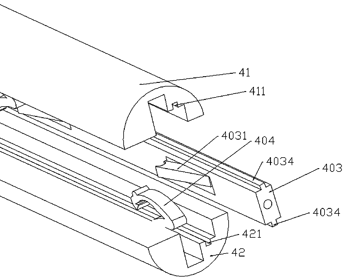
[0047] Specific embodiment 1: This embodiment discloses a flexible clip applier for a surgical robot, which includes an elongated part 4 and an articulating part and a driving end 2 located at both ends of the elongated part. The internal tension transmission device controls the opening and closing of the occlusal part. The pliers head includes a first occlusal part 501 and a second occlusal part 502 hinged to the first occlusal part. respectively provided with a snap connection part 503, such as Figure 17 As shown, the two occlusal joints are respectively provided with pull grooves 504, and the tension transmission device can be a movable rod 403. Under normal circumstances, the surgical robot transmits power to the driving end, and the driving end drives the occlusal part to open and close, but due to the operation of the robot The doctor is operating remotely and cannot sense the occlusal force of the occlusal part. Therefore, during operation, the occlusion of the clip ap...


PUM


Abstract

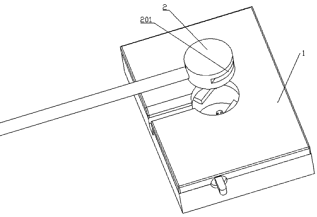
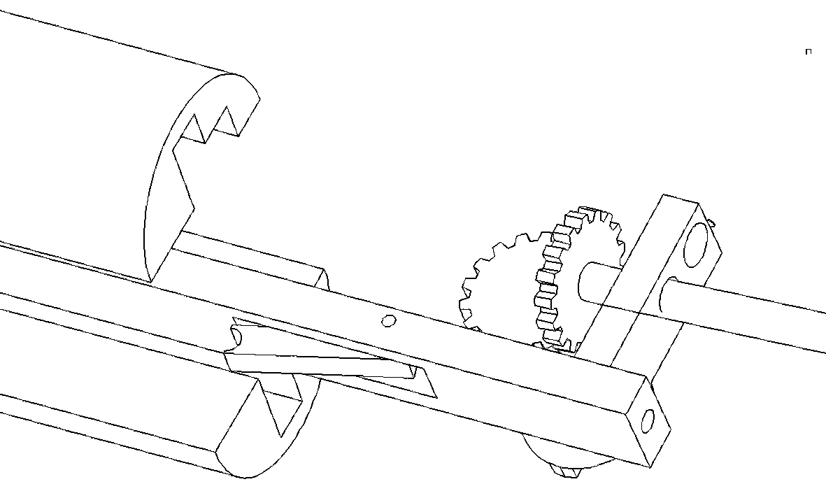
The invention discloses a driving mechanism of hemostasis clip applying pliers, and belongs to the field of medical instruments. The clip applying pliers comprises an extending portion, and a movablerod is arranged inside the extending portion; the driving mechanism comprises a driving end connected with the extending portion, a driving cavity is formed in the driving end and communicated with the interior of the extending portion, a driving tooth and a driven tooth are arranged in the driving cavity, the driving tooth is connected with an operation robot power device, and the driven tooth iscombined with the driving tooth to change the rotation direction of the driving tooth. A screw is fixedly connected with the driven tooth, a sliding block is connected to the screw and connected withthe tail end of the movable rod, and controls the movable rod to reciprocate in the axial direction of the extending portion; a limiting groove distributed in the axial direction is formed in the tail end of the movable rod, and a positioning rod which partially extends into the limiting groove in the movable rod is arranged on the side face of the driving cavity.

Description

technical field [0001] The invention relates to the field of hemostatic clip applicators. Background technique [0002] The hemostatic clip is a device used clinically to clamp blood vessels. The current hemostatic clip clamp is usually single-shot, and can only clamp one hemostatic clip at a time. After the hemostatic clip clamps the blood vessel, the hemostatic clip needs to be reinstalled. [0003] In some cases, there are also some multi-shot types, which can shoot multiple hemostatic clips at the same time. [0004] The existing hemostatic clip applier is controlled by a remote gun handle, and is usually applied to minimally invasive surgery. However, with the development of surgical robots, multi-mode clip appliers are applied to surgical robots and driven by robots. is a problem that needs to be solved. Contents of the invention [0005] The invention discloses a hemostatic clip clip applier driving mechanism, which can enable a surgical robot to control the clip ...

Claims


Application Information

Patent Timeline
Patent Type & Authority Applications(China)
IPC IPC(8): A61B17/128A61B34/00
CPCA61B17/1285A61B34/70A61B2017/12004
Inventor 不公告发明人
Owner THE AFFILIATED HOSPITAL OF QINGDAO UNIV
Learn More