Check patentability & draft patents in minutes with Patsnap Eureka AI!

Hydro forming press

A liquid-filled forming and press technology, which is applied in metal processing equipment, safety equipment, manufacturing tools, etc., can solve the problems of hidden safety hazards in the production process, increased tonnage of liquid-filled forming presses, and increased pressure on the mold clamping surface. Achieve the effect of avoiding frequent replacement and solving the problem of increasing the tonnage of the press

Active Publication Date: 2018-08-03
TSINGHUA UNIV
View PDF7 Cites 1 Cited by
  • Summary
  • Abstract
  • Description
  • Claims
  • Application Information

AI Technical Summary

Problems solved by technology

[0003] For liquid-filled forming presses, the current sealing method is to place the sealing ring on the end faces of the punch and die, that is, the clamping surface. When the punch and die are clamped and locked, the liquid can be effectively prevented. However, when the part is formed, take the sheet metal liquid-filled deep drawing as an example, as the sheet metal deep drawing process proceeds, the blank at the blank holder position will move to a certain extent. At this time, the sealing ring will follow the plate The material moves due to the movement of the mold. In the case of large clamping force, the wear of the sealing ring caused by this movement will be more serious, resulting in reduced reliability of the sealing ring, shortened life, and increased production costs.
In addition, if the position of the seal ring changes slightly, it will cause a large change in pressure
When considering changing the position of the sealing ring, that is, changing from the end face seal to the circumferential seal, due to the increase in the projected area of ​​the pressure on the mold clamping surface, the required tonnage of the press will increase, which will result in an increase in equipment manufacturing costs. Improve etc.
[0004] Therefore, if the sealing method of the liquid-filled forming press adopts the current method of placing the sealing ring on the mating surface of the punch and the die, there will be problems that the sealing ring is easy to wear and needs to be replaced frequently, and not only the cost is high , and the risk of leakage of the hydraulic medium due to the wear and tear of the sealing ring is prone to occur during the forming process; The projected area of ​​the clamping surface increases, resulting in an increase in the pressure on the clamping surface and an increase in the tonnage of the liquid-filled forming press. The above results will increase the manufacturing cost of the equipment and bring safety hazards to the production process.

Method used


Image

  • Hydro forming press
  • Hydro forming press

Examples


Embodiment Construction

[0018] The specific implementation manners of the present invention will be further described in detail below in conjunction with the accompanying drawings and embodiments. The following examples are used to illustrate the present invention, but are not intended to limit the scope of the present invention.

[0019] In the description of the present invention, it should be noted that the orientation or positional relationship indicated by the terms "middle", "concave", "convex", "vertical", "horizontal", "inner" and "outer" are based on the attached The orientation or positional relationship shown in the figure is only for the convenience of describing the present invention and simplifying the description, and does not indicate or imply that the referred device or element must have a specific orientation, be constructed and made in a specific orientation, so it cannot be understood as a Invention Limitations.

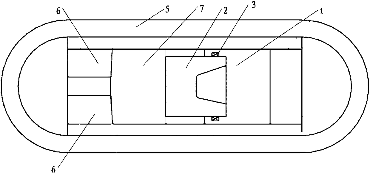
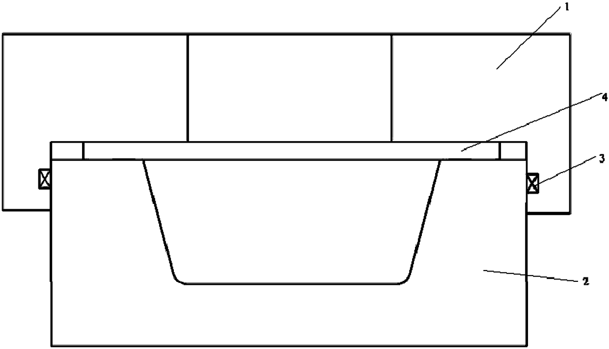
[0020] figure 1 It is a schematic diagram of a liquid-filled form...


PUM


Abstract

The invention provides a hydro forming press. The hydro forming press comprises a male die, a female die, a sealing ring, a movable beam, a machine frame and multiple wedge blocks; the male die and the female die are arranged in the machine frame in a matched mode, the sealing ring is annularly clamped on the circumferential contact surfaces between the male die and the female die, and the sealingring is fixedly connected to the male die or the female die; and the movable beam is arranged between the female die and one end of the machine frame, the multiple wedge blocks with inclined surfacelifting angles smaller than 10 degrees are arranged between the movable beam and one end of the machine frame, the inclined surfaces of the wedge blocks are attached to the movable beam, and the bottoms of the wedge blocks are attached to one end of the machine frame. According to the hydro forming press, the sealing ring moves from the die closing surfaces between the male die and the female dieto the circumferential contact surfaces between the male die and the female die, meanwhile, the wedge blocks capable of self-locking are clamped between the movable beam and the bottom of the machineframe, the pressure of the mold closing surfaces is transmitted to the machine frame through the wedge blocks, so that the stress of the press keeps stable, the press is not prone to be damaged, and the tonnage of the press is not increased; and meanwhile, the service life of the sealing ring is prolonged, and the risk of leakage of a liquid medium in the frequent replacement process of the sealing ring is avoided.

Description

technical field [0001] The invention relates to the field of liquid-filled forming machines, in particular to a liquid-filled forming press. Background technique [0002] Hydroforming technology uses liquid media such as oil, water, and special fluid media to replace rigid molds to transmit loads, so that the sheet can be attached to the punch or die under the pressure of the hydraulic medium, and the pressure of the fluid medium and the blank holder force are controlled to make The part is formed into the desired shape. Therefore, there are relatively high sealing and tonnage requirements for the corresponding equipment. [0003] For liquid-filled forming presses, the current sealing method is to place the sealing ring on the end faces of the punch and die, that is, the clamping surface. When the punch and die are clamped and locked, the liquid can be effectively prevented. However, when the part is formed, take the sheet metal liquid-filled deep drawing as an example, as...

Claims


Application Information

Patent Timeline
Patent Type & Authority Applications(China)
IPC IPC(8): B21D26/02B21D26/029B21D26/045B21D55/00
Inventor 吴任东袁朝龙魏玮焦玮黄佳杰姜艺林周洁陈福强
Owner TSINGHUA UNIV
Features
  • R&D
  • Intellectual Property
  • Life Sciences
  • Materials
  • Tech Scout
  • Unparalleled Data Quality
  • Higher Quality Content
  • 60% Fewer Hallucinations
Learn More