
Slag soil improvement construction device and method for shield construction

A technology for improving dregs and construction equipment, which is applied in the direction of earth cube drilling, mining equipment, tunnels, etc., which can solve the problems of difficult maintenance of soil pressure balance on the excavation surface, instability of the excavation surface, and high permeability of the formation, and achieve the goal of improving dregs. Effects of Soil Flow Plasticity and Permeability

Pending Publication Date: 2018-08-03
CHINA UNIV OF MINING & TECH (BEIJING)
View PDF9 Cites 2 Cited by
  • Summary
  • Abstract
  • Description
  • Claims
  • Application Information

AI Technical Summary

Problems solved by technology

When the shield machine passes through complex strata such as water-rich sand layers, the stratum has high permeability, poor fluidity and plasticity of the soil, severe wear of the cutter head and screw conveyor, and the soil pressure balance of the excavation surface is not easy to maintain, and it is easy to collapse; the tunnel passes through water-rich silt sand 1. The sandy silt layer has the characteristics of seepage and liquefaction. Under the action of dynamic water pressure, it is easy to cause problems such as instability of the excavation surface, blockage of the pressure chamber, cake formation in the pressure chamber, and gushing.
[0003] In the process of realizing the present invention, the inventors found that there are at least the following problems in the prior art: When constructing in areas with rich water and coarse sand layers, technical problems such as gushing and poor flow plasticity are likely to occur

Method used

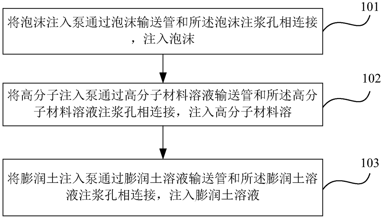

Image

  • Slag soil improvement construction device and method for shield construction
  • Slag soil improvement construction device and method for shield construction
  • Slag soil improvement construction device and method for shield construction

Examples


Embodiment Construction

[0019] The following will clearly and completely describe the technical solutions in the embodiments of the present invention with reference to the accompanying drawings in the embodiments of the present invention. Obviously, the described embodiments are only some, not all, embodiments of the present invention. Based on the embodiments of the present invention, all other embodiments obtained by persons of ordinary skill in the art without making creative efforts belong to the protection scope of the present invention.

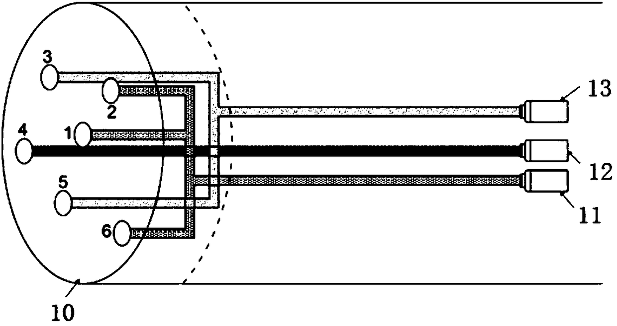
[0020] Such as figure 1 As shown, it is a schematic structural diagram of a muck improvement construction device for shield construction according to an embodiment of the present invention, and the device includes:

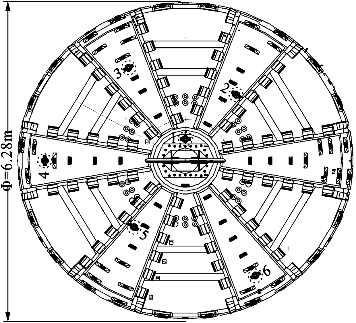
[0021] A shield cutter head 10, on which at least three grouting holes are set outward from the center of the circle: a foam grouting hole, a bentonite solution grouting hole, and a polymer material solution grouting hole 4;

[0022] A foam injec...


PUM


Abstract

The embodiment of the invention provides a slag soil improvement construction device and method for shield construction. The device comprises a shield cutter head, a foam injection pump, a polymer injection pump and a bentonite injection pump; at least three grouting holes are formed in the shield cutter head from the center position to the outside, and the three grouting holes include a foam grouting hole, a bentonite solution grouting hole and a polymer material solution grouting hole; the foam injection pump is connected with the foam grouting hole through a foam conveying pipe; the polymerinjection pump is connected with the polymer material solution grouting hole through a polymer material solution conveying pipe; the bentonite injection pump is connected with the bentonite solutiongrouting hole through a bentonite solution conveying pipe. The device ensures the smooth tunneling of a shield, the foam injection hole ensures that the foam plays a role in reducing the resistance tothe cutter head, and the bentonite solution grouting hole and the polymer material solution grouting hole achieve the purpose of improving the flow plasticity and permeability of slag soil during theconstruction of a coarse sand layer zone in the rich water.

Description

technical field [0001] The invention relates to the technical field of shield tunneling, in particular to a dregs improvement construction device and method for shield tunneling. Background technique [0002] In the construction of earth pressure balance shield, it is necessary to improve the soil in front of the excavation face to maintain the stability of the face and increase the excavation efficiency. When the shield passes through complex strata such as water-rich sand layers, the stratum has high permeability, poor flow plasticity of the soil, severe wear of the cutter head and screw conveyor, and the soil pressure balance of the excavation surface is difficult to maintain, and it is easy to collapse; the tunnel passes through water-rich silt sand 1. The sandy silt layer has the characteristics of seepage and liquefaction, and under the action of dynamic water pressure, it is easy to cause problems such as instability of the excavation surface, blockage of the pressure...

Claims


Application Information

Patent Timeline
Patent Type & Authority Applications(China)
IPC IPC(8): E21D9/08E21D9/06
CPCE21D9/0678E21D9/08
Inventor 杨志勇丁彦杰江玉生江华张加健
Owner CHINA UNIV OF MINING & TECH (BEIJING)
Learn More