An ultraviolet light LED light source device

A technology of LED light source and ultraviolet light, applied in the field of LED light source, can solve the problems of insufficient light concentration, insufficient energy, high density at long distance, etc., and achieve the effect of good linear light spot

Pending Publication Date: 2018-08-03
深圳市优绿源科技有限公司
View PDF0 Cites 3 Cited by
  • Summary
  • Abstract
  • Description
  • Claims
  • Application Information

AI Technical Summary

Problems solved by technology

However, the traditional UV LED light source generally has the problems of insufficient light concentration and insufficient long-distance high-density and high-energy

Method used


Image

  • An ultraviolet light LED light source device
  • An ultraviolet light LED light source device
  • An ultraviolet light LED light source device

Examples


Embodiment Construction

[0025] In order to make the object, technical solution and advantages of the present invention clearer, the present invention will be further described in detail below in conjunction with the accompanying drawings and embodiments. It should be understood that the specific embodiments described here are only used to explain the present invention, not to limit the present invention. On the contrary, the purpose of providing these embodiments is to make the disclosure of the present invention more thorough and comprehensive.

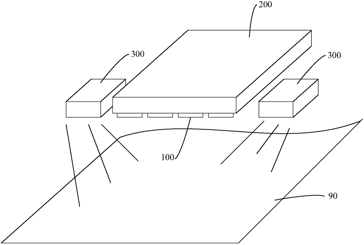
[0026] figure 1 It is a structural schematic diagram of an ultraviolet LED light source device according to an embodiment. The ultraviolet LED light source device 10 includes an LED light source module 100 , a heat dissipation module 200 and an oxygen-free gas source 300 arranged in an array. The oxygen-free gas source 300 is used to blow gas to the irradiating surface 90 of the LED light source module 100 to create an oxygen-free environment on the irrad...


PUM


Abstract

The invention relates to an ultraviolet light LED light source device including a LED light source module and a heat radiation module. The LED light source module includes a substrate and LED light source units arranged in an array on the substrate. The substrate is installed on the heat radiation module and the ultraviolet light LED light source device also includes an oxygen-free gas source. Theoxygen-free gas source is used to blow oxygen-free gas on the irradiation surface of the LED light source module and to create an oxygen-free environment on the irradiation surface of the LED light source module. The above ultraviolet light LED light source device is equipped with the oxygen-free gas source, the oxygen-free gas source blow the oxygen-free gas to the irradiation surface during theultraviolet irradiation, the oxygen concentration in the upper space of the irradiation surface can be diluted, the oxygen concentration can be reduced to a lower degree through the continuous blowing, thus the oxygen-free environment is formed. Due to a fact that no ozone may be generated in an oxygen-free environment when ultraviolet rays irradiate on the irradiation surface, so that the quality of the ultraviolet ray irradiation solidification is ensured.

Description

technical field [0001] The invention relates to an LED light source, in particular to an ultraviolet LED light source device. Background technique [0002] Ultraviolet light LED light source devices are mostly used in processes that adopt ultraviolet light irradiation and curing, such as photolithography curing and printing curing processes. [0003] Because ultraviolet rays can cause the ionization of oxygen in the air, ozone is produced. The activity of ozone is higher, and ozone will be generated in the area where the ultraviolet energy gathers, that is, the ultraviolet irradiation surface, and this is the area where the cured material is located. In some processes, such as printing processes, some printing materials will be oxidized by ozone, resulting in a lower printing pass rate. Ozone also absorbs and blocks UV rays, making UV energy exposure less effective. [0004] In addition, in the printing process, the ultraviolet LED light source usually needs to provide a ...

Claims


Application Information

Patent Timeline
Patent Type & Authority Applications(China)
IPC IPC(8): F21K9/20F21V19/00F21V29/56F21V29/60F21V29/74F21V29/89F21Y115/10
CPCF21V19/001F21V29/56F21V29/60F21V29/74F21V29/89
Inventor 郑舜川
Owner 深圳市优绿源科技有限公司
Why Eureka
Try Eureka