A ct imaging method

A CT imaging and imaging technology, applied in image generation, image data processing, 2D image generation, etc., can solve problems such as poor reconstruction effect, and achieve the effect of saving computing time, saving computing resources, and simple and clear algorithms

Active Publication Date: 2021-04-02
CENT SOUTH UNIV +1
View PDF7 Cites 0 Cited by
  • Summary
  • Abstract
  • Description
  • Claims
  • Application Information

AI Technical Summary

Problems solved by technology

The CT imaging method provided by this reference file does not involve iterative steps in the algorithm, which can shorten the calculation time, but the reconstruction effect is not good

Method used


Image

  • A ct imaging method
  • A ct imaging method
  • A ct imaging method

Examples


Embodiment 4

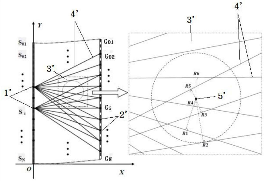
[0096] Embodiment 4: Seismic wave CT imaging method for detecting underground three-dimensional geological structure

[0097] Such as Figure 4 As shown, four drill holes ZK01, ZK02, ZK03, and ZK04 with a depth of 30m and a square distribution of 15 meters have been completed on the horizontal ground. Select a pair of boreholes to carry out the seismic wave CT detection operation, and there are 6 pairs of boreholes in total. One is used as a transmitting hole, and the distance between the transmitting source point (source point 1”) is 1m, and there are 31 points in total; the other is used as a receiving hole, and the distance between the receiving point (observation point 2”) is 1m, which is also 31 points. The emission source point (source point 1") and the receiving point (observation point 2") move synchronously or interlaced point by point, use the seismograph to record the travel time difference of the seismic wave, convert it into the velocity on each seismic wave trav...


PUM


Abstract

The invention discloses a CT imaging method. The method comprises the following steps of: establishing a coordinate system which covers a detected area, source points and observation points; obtainingand setting coordinates of the source points and the observation points as parameters 1, calculating and setting a source point-observation point linear equation as a parameter 2, and arranging a measurement calculation result on each pair of source point-observation point line as a parameter 3; establishing a parameter database according to the parameters 1, the parameter 2 and the parameters 3;determining a calculation area, discretizing the calculation area into quasi-calculation image points, and obtaining a coordinate parameter 4 of each image point; respectively taking a quasi-calculation image point to set an enrolling rule and an enrolling line, calculating a distance Ri from each image point to the enrolling line and recording the total number M of the enrolling lines; accumulating weight parameters 3 which take Ri as association and act on the parameter 3 corresponding to the image point according to a distance inverse ratio rule, and carrying out averaging by the M value so as to obtain a parameter value 5 of the image point; and carrying out global imaging via the parameter value 5. The method does not need to construct and solve equation sets by using the traditionalCT method, does not need iterative calculation and is wide in application fields.

Description

technical field [0001] The invention belongs to the technical field of computer imaging, and in particular relates to a CT imaging method, which can be widely used in the imaging of data collected by technologies such as electromagnetic wave CT, ultrasonic CT, conductive electric field CT, and seismic wave CT, and is applicable to medicine, industry, security inspection, nondestructive testing and Geophysical exploration and many other fields. Background technique [0002] CT (Computed Tomography, referred to as CT) is the abbreviation of "Computed Tomography". It was successfully designed by Hounsfield G.N. in 1969 and came out in 1972. CT is to use X-ray beams to scan the layer with a certain thickness of the human body inspection part from multiple directions. The X-rays passing through this layer are received by the detector instead of film, and after being converted into visible light, it is converted into an electrical signal by a photoelectric converter. It is then c...

Claims


Application Information

Patent Timeline
Patent Type & Authority Patents(China)
IPC IPC(8): G06T11/00
CPCG06T11/005G06T2211/00
Inventor 朱德兵李小罗冯德山刘海飞贾朋涛钟兆泓陶望雄张爱恒汤自权张磊严武平
Owner CENT SOUTH UNIV
Why Eureka
Try Eureka