
Terminal and electric connector equipped with same

An electrical connector and terminal technology, applied in the direction of conductive connection, connection, fixed connection, etc., can solve the problems of wasting solder, short-circuiting adjacent terminals, etc., and achieve the effect of saving solder

Active Publication Date: 2018-08-03
DEYI PRECISION ELECTRONIC IND CO LTD PANYU
View PDF6 Cites 2 Cited by
  • Summary
  • Abstract
  • Description
  • Claims
  • Application Information

AI Technical Summary

Problems solved by technology

However, too much solder is required to cover the entire soldering portion, which is a waste of solder, and as the density of terminals in the electrical connector increases, when too much solder is soldered to the terminals, it is easy to cause gaps between adjacent terminals. Shorting of

Method used


Image

  • Terminal and electric connector equipped with same
  • Terminal and electric connector equipped with same
  • Terminal and electric connector equipped with same

Examples


Embodiment Construction

[0034] In order to facilitate a better understanding of the purpose, structure, features, and effects of the invention, the present invention will now be further described in conjunction with the accompanying drawings and specific embodiments.

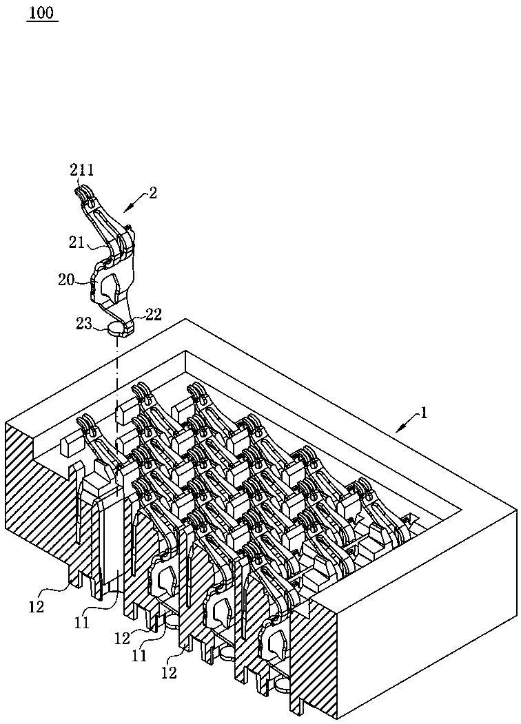
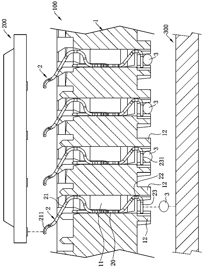
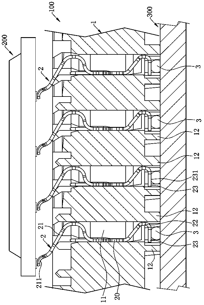
[0035] Such as figure 1 and image 3 Shown is the first embodiment of the electrical connector 100 of the present invention, which includes: an insulating body 1 and a plurality of terminals 2 disposed on the insulating body 1, the electrical connector 100 is used to electrically connect a chip The module 200 is connected to a circuit board 300 .

[0036] Such as figure 2 As shown, the insulating body 1 has a plurality of receiving holes 11 that penetrate up and down, and a plurality of the terminals 2 are correspondingly accommodated in the plurality of receiving holes 11, and the lower surface of the insulating body 1 corresponds to each of the receiving holes. A plurality of protruding parts 12 extend downward around the periphe...


PUM


Abstract

Disclosed is an electric connector for electrically connecting a chip module to a circuit board. The electric connector comprises an insulation body and at least one terminal, wherein at least one accommodating hole which runs through up and down is formed in the insulation body; each accommodating hole correspondingly accommodates one terminal; each terminal has a contact part at the upper end and a welding part at the lower end; the welding part extends downwardly out of the corresponding accommodating hole; the welding part has a welding surface and a solder resist layer for surrounding thewelding surface; the welding surface is used for combining a soldering flux; and the solder resist layer is used for blocking diffusion of the soldering flux on the solder resist layer.

Description

technical field [0001] The invention relates to a terminal and an electrical connector with the terminal, in particular to a terminal for preventing solder from siphoning and an electrical connector with the terminal. Background technique [0002] An existing electrical connector has an insulating body, and a plurality of terminals are arranged on the insulating body. The terminal has a main body and a welding part extending downward from the main body. The welding part is welded to the circuit board by solder, in order to prevent When the solder and the terminal are soldered, tin creeping occurs, and a diffusion prevention area is formed by laser at the joint between the soldering part and the main body. When the solder melts into a liquid state, it covers the entire soldering part. The diffusion prevention area can prevent the liquid solder from climbing to the main body. However, too much solder is required to cover the entire soldering portion, which is a waste of solde...

Claims


Application Information

Patent Timeline
Patent Type & Authority Applications(China)
IPC IPC(8): H01R12/57H01R12/71H01R13/02H01R33/74H01R4/02
CPCH01R4/028H01R12/57H01R12/716H01R13/02H01R33/74
Inventor 何建志
Owner DEYI PRECISION ELECTRONIC IND CO LTD PANYU
Learn More