Permanent magnet synchronous motor back potential harmonic suppressing method and permanent magnet synchronous motor

A permanent magnet synchronous motor, harmonic suppression technology, applied in permanent magnet synchronous motor back EMF harmonic suppression, permanent magnet synchronous motor field, can solve the problem that there is no way to suppress the back EMF harmonic and weaken the permanent magnet synchronous motor back EMF harmonic And other issues

Active Publication Date: 2018-08-03
NIDEC KAIYU AUTO ELECTRIC JIANGSU
View PDF5 Cites 4 Cited by
  • Summary
  • Abstract
  • Description
  • Claims
  • Application Information

AI Technical Summary

Problems solved by technology
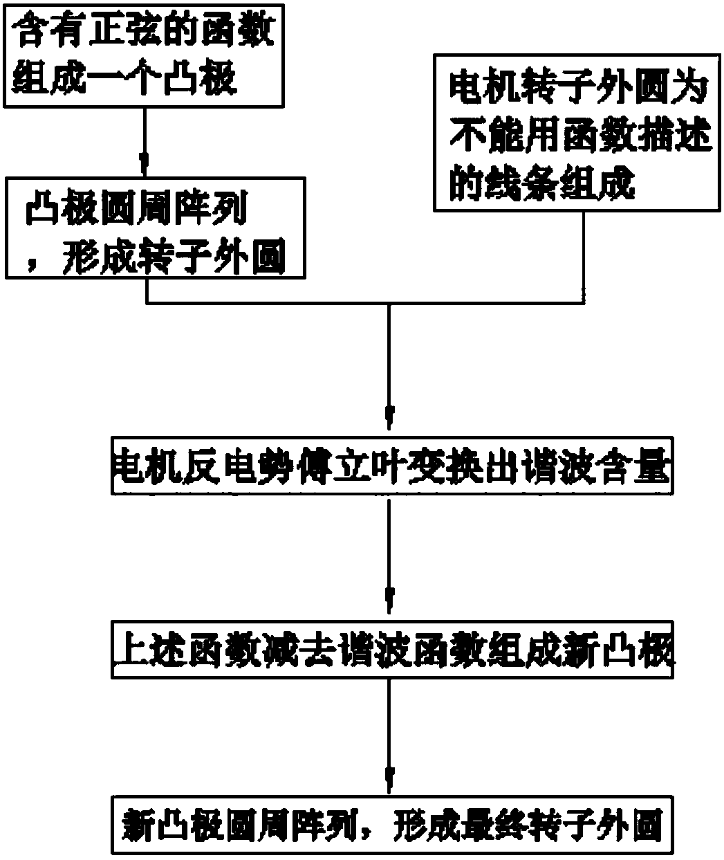
Starting from the motor itself, such as the motor literature "Magnetic Pole Shape Optimization Method for Weakening the Back EMF Harmonic of Permanent Magnet Synchronous Motor", Micro Motor, 2017, 50(2): 24-26, established a description equation for the sine arc profile of the magnetic pole surface, but There is no way to suppress back emf harmonics of a specific order

Method used


Image

  • Permanent magnet synchronous motor back potential harmonic suppressing method and permanent magnet synchronous motor
  • Permanent magnet synchronous motor back potential harmonic suppressing method and permanent magnet synchronous motor
  • Permanent magnet synchronous motor back potential harmonic suppressing method and permanent magnet synchronous motor

Examples


Embodiment 1

[0013] The motor in the embodiment of the present invention has 12 slots and 8 poles, IPM structure, and sine wave control. The air gap is 0.4mm.

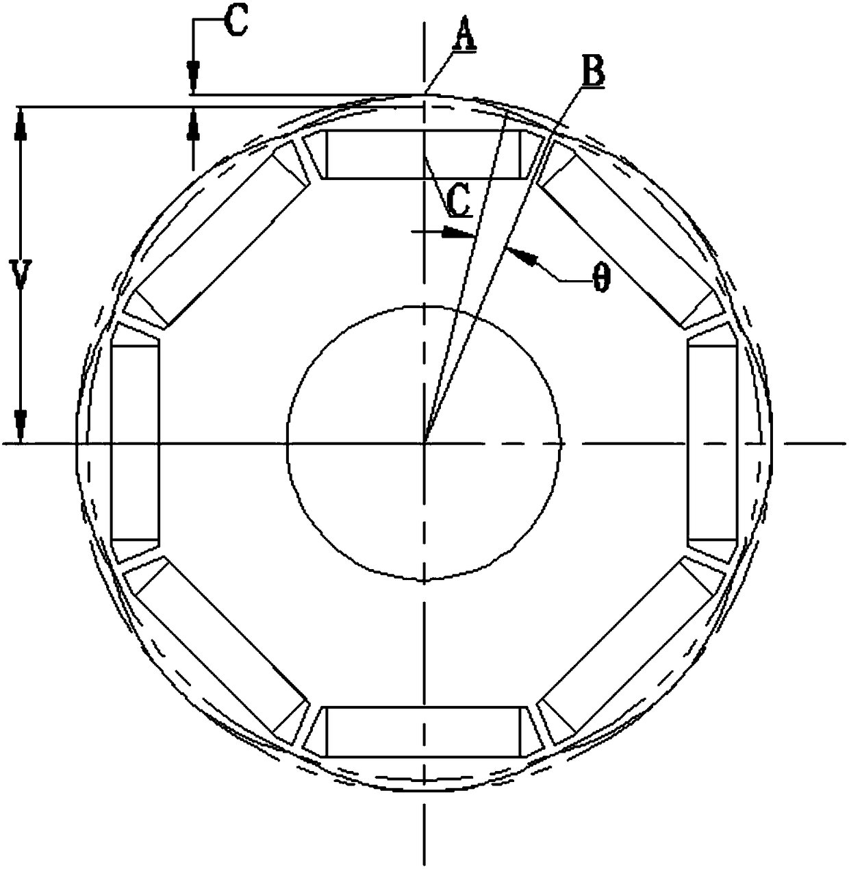
[0014] Functions involving sine take: Among them, v and c are taken as 20.9mm and 0.7mm respectively. Draw a salient pole, and for this salient pole circular array, the array number is equal to the pole number 8.

[0015] The connection line between the apex of the salient pole and the center of the circle passes through the geometric center of the magnet, and the connection line between the lowest point of the salient pole and the center of the circle passes through the boundary between two adjacent magnetic steels. The minimum distance from the vertex of the salient pole to the inner circle of the stator is 0.4mm in the air gap of the motor. Draw the shape of the motor rotor figure 1 .

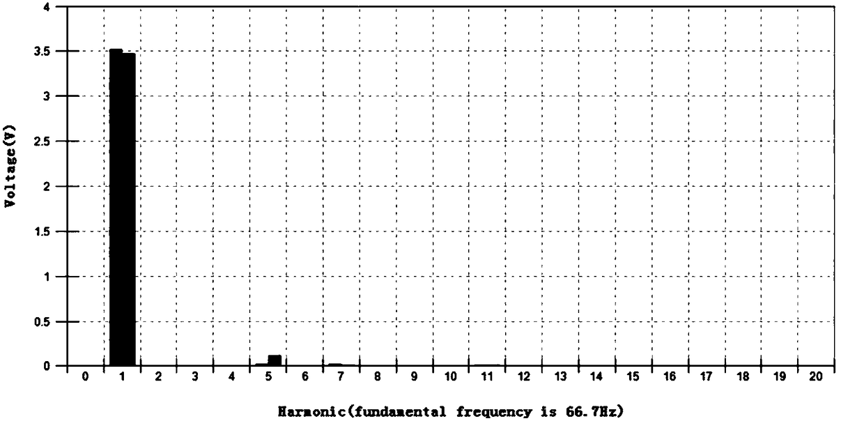
[0016] In the case that the stator and rotor have no oblique poles, test the back EMF waveform of the motor containing the above rotor, an...

Embodiment 2

[0020] The motor in the embodiment of the present invention has 12 slots and 10 poles, IPM structure, and sine wave control. The air gap is 0.2mm.

[0021] Functions involving sine take: Among them, v and c are taken as 21mm and 0.7mm respectively. Draw a salient pole, and for this salient pole circular array, the number of arrays is equal to 10 poles.

[0022] The connection line between the apex of the salient pole and the center of the circle passes through the geometric center of the magnet, and the connection line between the lowest point of the salient pole and the center of the circle passes through the boundary between two adjacent magnetic steels. The minimum distance from the vertex of the salient pole to the inner circle of the stator is 0.2mm for the air gap of the motor. Draw the shape of the motor rotor.

[0023] In the case that the stator and rotor have no oblique poles, test the back EMF waveform of the motor containing the above rotor, and perform Fourie...


PUM


Abstract

The invention discloses a permanent magnet synchronous motor back potential harmonic suppressing method. The method comprises the steps that a function containing a sine forms a salient pole; the salient pole forms the excircle of a motor rotor through a circumferential array, or the excircle of the motor rotor is composed of a line which cannot be described by a function; the back potential waveform of a motor is tested; the harmonic order and amplitude are decomposed through Fourier transform; the sinusoidal function subtracts a harmonic function to form a new salient pole; and the new salient pole finally forms the excircle of the motor rotor through the circumferential array. Motor air gaps made by the method are sinusoidally distributed. An excircle function subtracts the back potential harmonic function. The back potential harmonic result is suppressed. The method has the advantages of simple and effective principle, strong operability, low motor back potential harmonic content,small torque fluctuation and low vibration noise.

Description

[0001] The invention relates to a method for suppressing back EMF harmonics of a permanent magnet synchronous motor and the permanent magnet synchronous motor, in particular to a method for suppressing the back EMF of a sine wave controlled permanent magnet synchronous motor. Background technique [0002] The harmonics of the permanent magnet motor current will cause vibration and noise of the motor, increase the heat generation, and reduce the efficiency of the motor. Suppression of permanent magnet motor current harmonics can start from two aspects of control and motor body. Starting from the control aspect, such as the invention patent application with the application number 201110145038.4 "A Control Method for Injecting Harmonic Voltage to Suppress Harmonic Current of Permanent Magnet Synchronous Motor", which discloses injecting harmonic voltage components into the three-phase control voltage to offset harmonic components of the current, but reduces the efficiency of the ...

Claims


Application Information

Patent Timeline
Patent Type & Authority Applications(China)
IPC IPC(8): H02K21/02H02K1/27
CPCH02K1/276H02K1/278H02K21/02H02K2213/03
Inventor 王咏涛邱高峰王朝海
Owner NIDEC KAIYU AUTO ELECTRIC JIANGSU
Why Eureka
Try Eureka