
Device and method for smoking cigarettes

A technology for cigarettes and smokers, which is applied in the field of electronic devices that directly ignite and smoke ordinary commercially available cigarettes, and can solve problems such as difficulty in cleaning, ignition failure, and difficulty in determining the exact position of the cigarette end

Pending Publication Date: 2018-08-07
深圳维昔技术有限公司
View PDF0 Cites 2 Cited by
  • Summary
  • Abstract
  • Description
  • Claims
  • Application Information

AI Technical Summary

Problems solved by technology

But its defect is also very obvious, and this prior art has adopted the mode of mobile ignition, and this makes combustion chamber can not be completely isolated from electromechanical equipments such as motor, screw rod, and cigarette can produce a large amount of tar and dust in burning process After a long time, it will inevitably adhere to the relevant electromechanical equipment, which is difficult to clean and can easily lead to failure; secondly, because it uses a heating wire as the ignition device, it needs to wait for a certain period of time before the temperature can be raised to the ignition point of the cigarette. It takes a long time. In addition, tar and dust will also adhere to the heating wire. If it accumulates to a certain extent, it will take longer for the heating wire, and even it is difficult to light a cigarette, and ignition failures will often occur. Finally, the mobile ignition method still exists. A very big problem is that it is difficult to determine the exact position of the cigarette butt, and of course it is even more difficult to accurately move the heating wire to the position where the cigarette is to be lit for precise ignition

Method used


Image

  • Device and method for smoking cigarettes
  • Device and method for smoking cigarettes
  • Device and method for smoking cigarettes

Examples


no. 1 example

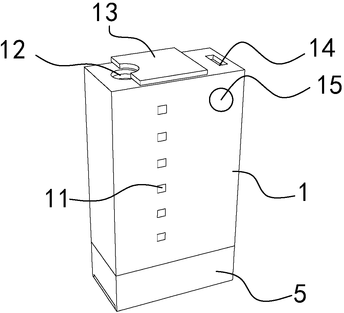
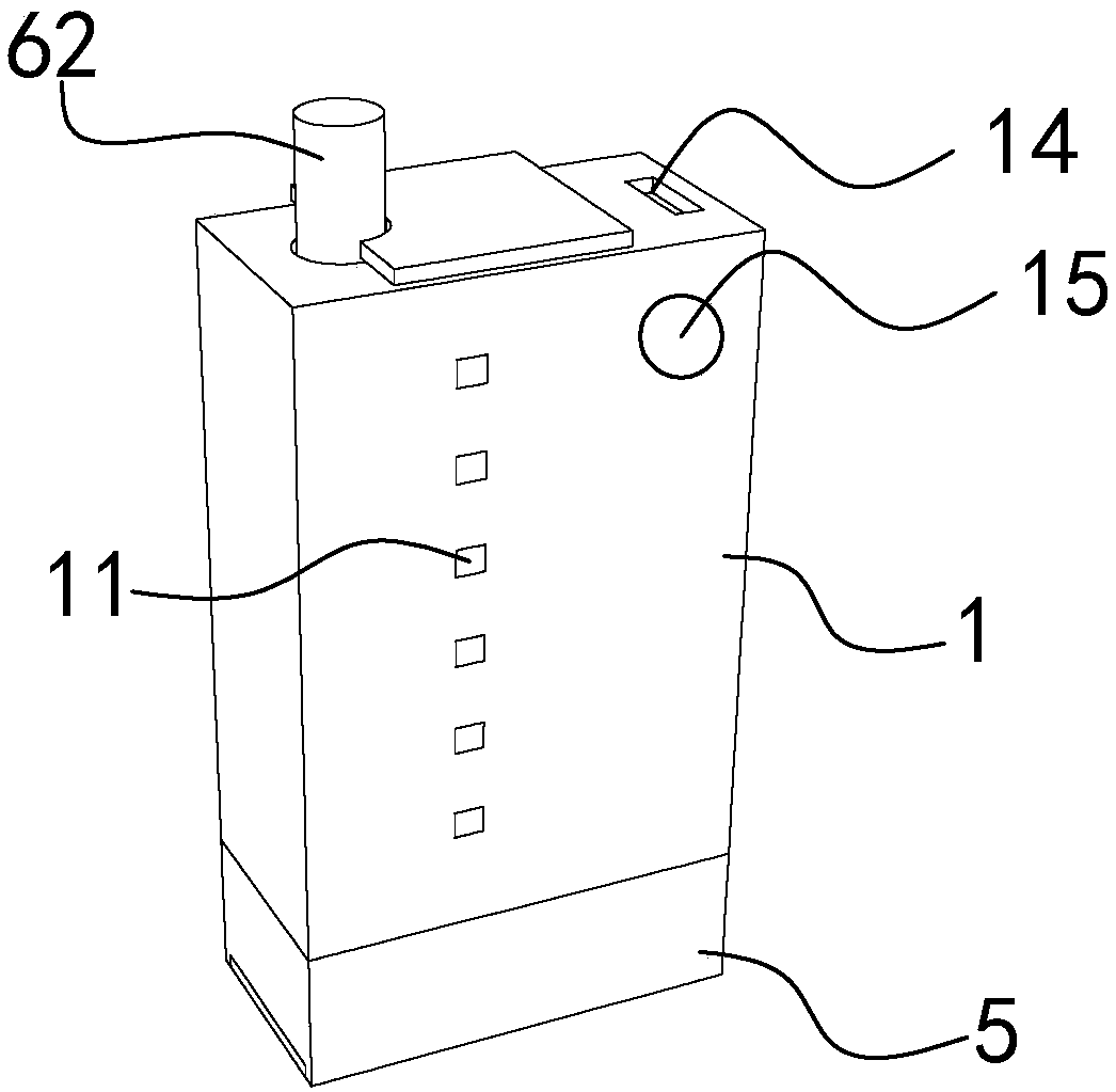
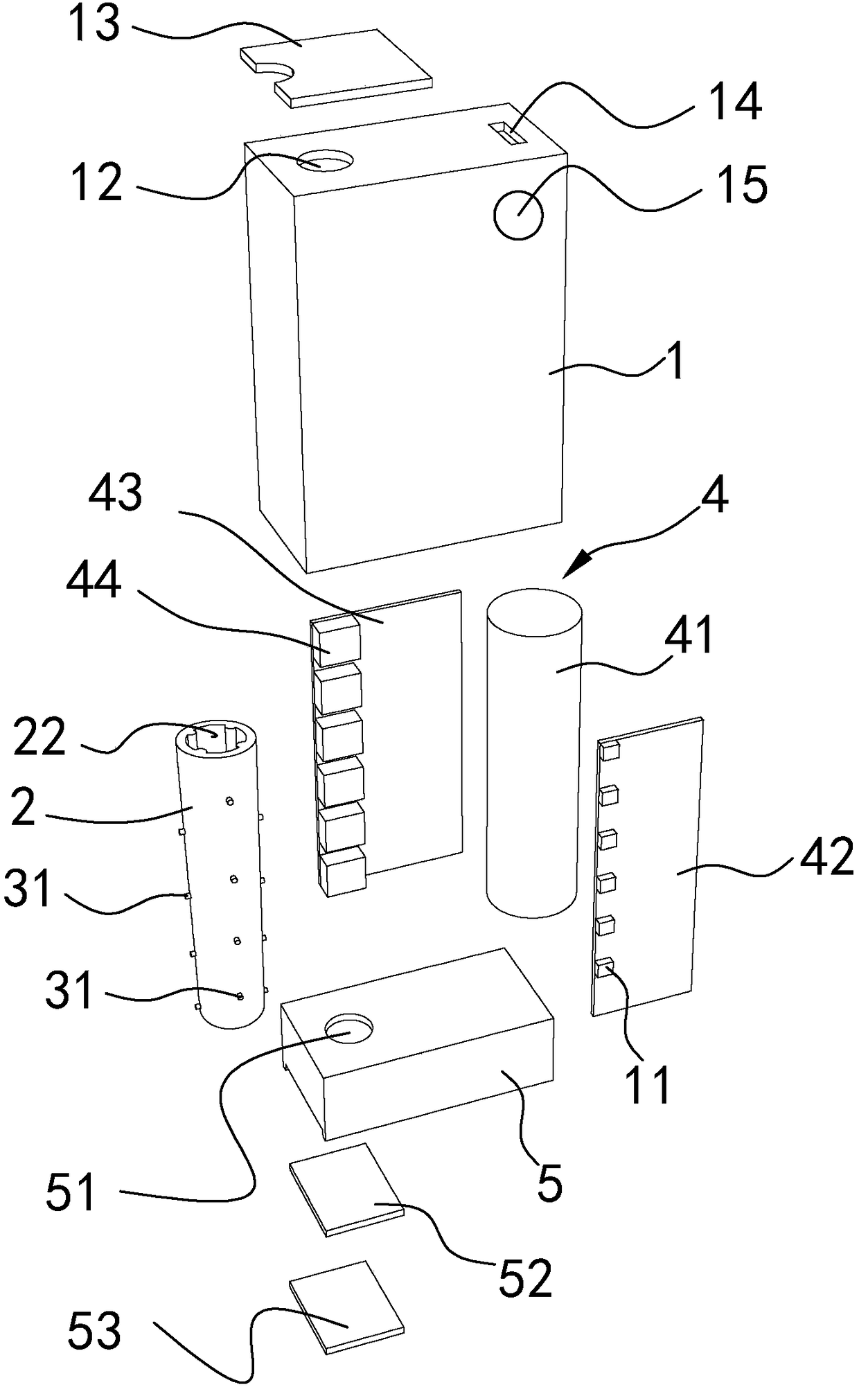
[0038] all attached Figure 1-10 All only disclose the part closely related to the present invention, but not the whole structure. like Figure 1-9 The first embodiment of the invention shown is an electronic device for directly lighting and smoking a conventional commercially available cigarette. The so-called "cigarette" in the present invention refers to commercially available ordinary cigarettes with filters, and according to national standards, the length (including filters) is mainly 84mm. The so-called "lighting" of the present invention means that the cigarette must be burned after reaching the ignition point, and any mode that only heats and does not burn is not within this scope. like Figure 3-5 As shown, the device includes a box-shaped main body 1, and components such as a combustion tube 2, an arc generating assembly 3, a power supply assembly 4 and a control assembly are arranged in the main body 1. The combustion tube 2 is generally made of high-temperatu...


PUM


Abstract

The invention relates to an electronic device and method for directly igniting and smoking common marketing cigarettes. The device comprises a combustion pipe, at least three arc generation components, a power component and a control component, the arc generation components are mutually and axially arranged on the combustion pipe at intervals, and the control component can successively drive the all arc generation components to ignite the cigarettes. The smoking method includes the steps: inserting a cigarette into the combustion pipe, driving the arc generation component at the most front endto ignite the cigarette, smoking first cigarette by matching with an aspiratory action, and immediately extinguishing the cigarette; when preset conditions are met, igniting the cigarette by an adjacent arc generation component by a control device; cycling the steps until the cigarette is completely smoked. According to the device and the method, the cigarette in the combustion pipe is relativelyand accurately ignited by a sectioning fixed ignition mode, the characteristic that an electric arc moves along the direction of air flow is skillfully used, and the overall cigarette is smoked by matching with aspiratory action of a smoker.

Description

technical field [0001] The invention relates to the technical field of smoking appliances, in particular to an electronic device and method for directly lighting and smoking common commercially available cigarettes. Background technique [0002] Cigarettes are a kind of tobacco products, which are made by drying the tobacco, cutting it into shreds, and then rolling it into a drum shape with paper. When inhaling, light one end and inhale the smoke from the other end. In order to reduce the smog, edible oil and suspended particles produced during the intake of smoking, modern cigarettes are also equipped with a filter tip at one end of smoking. It is an indisputable fact that smoking cigarettes will damage the health of the smoker, and the smoke and ash produced during the smoking process will also damage the physical and mental health of the surrounding people and pollute the environment. [0003] Currently the most popular alternative is electronic cigarettes, which use el...

Claims


Application Information

Patent Timeline
IPC IPC(8): A24F13/00
CPCA24F13/00
Inventor 张雪松胡香衡
Owner 深圳维昔技术有限公司
Learn More