a restrictor valve

A flow limiting valve and valve body technology, applied in the field of flow limiting valves, can solve the problems that the flow limiting valve is vulnerable to impact, etc., and achieve the effects of reducing the flow rate of the valve, preventing damage, and increasing the size

Active Publication Date: 2020-03-17
NORTH CHINA UNIV OF WATER RESOURCES & ELECTRIC POWER
View PDF6 Cites 0 Cited by
  • Summary
  • Abstract
  • Description
  • Claims
  • Application Information

AI Technical Summary

Problems solved by technology

[0003] The technical problem to be solved by the present invention is: to overcome the technical problem that the closing of the flow limiting valve is easy to be impacted in the prior art, and to provide a flow limiting valve

Method used


Image

  • a restrictor valve

Examples


Embodiment Construction

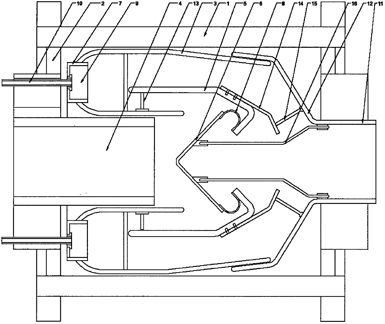
[0016] The present invention is described in further detail now in conjunction with accompanying drawing. These drawings are all simplified schematic diagrams, which only illustrate the basic structure of the present invention in a schematic manner, so they only show the configurations related to the present invention.

[0017] like figure 1 As shown, the present invention is a flow limiting valve, including a valve body casing, and the lateral sides of the valve body casing are respectively provided with a left connection cover and a right connection cover; wherein the left connection cover is provided with an inlet A water connection pipe, the outer wall of the water inlet connection pipe is provided with an annular turnback water pipe, one axial end of the turnback water pipe is a closed structure, and the other end is an open structure, and the end of the water inlet connection pipe is also provided with a Return water pipe, one end of the return water pipe is a closed st...


PUM


Abstract

The invention relates to a flow-limiting valve which comprises a valve body shell. A water inlet connecting pipe is arranged on the left side of the valve body shell, an annular return water pipe is arranged on the outer wall of the water inlet connecting pipe, a reflux water pipe is further arranged at the end of the water inlet connecting pipe, the outer wall of the reflux water pipe is in sleeve connection with the inside of the return water pipe through the inner wall of the return water pipe, a conical reflux plate is arranged inside the reflux water pipe and connected in the middle of the reflux water pipe through an annular elastic supporting ring, a drain pipe is arranged on a right connecting cover of the valve body shell, a drain cover with a convergent structure is connected onto the drain pipe, a necking end of the drain cover is connected with the drain pipe, the drain pipe is connected onto the annular inner wall of a movable sleeve through a plurality of connecting rods,the conical back of the reflux plate is connected onto the drain pipe through a plurality of elastic connecting rods, a plurality of supporting spring pieces are annularly arrayed on the outer wall of the reflux water pipe, and a plurality of supporting rods are annularly arrayed on the drain cover and contact with the supporting spring pieces.

Description

technical field [0001] The invention relates to a flow limiting valve, which belongs to the field of valves. Background technique [0002] The traditional flow limiting valve uses a floating piston block, which is connected by a spring, and uses the water flow to impact the piston block to realize the floating of the piston block, so that the valve can be closed when the water flow is too fast. The size of the gap between the inner walls is limited, it is easy to be blocked, and when the valve is closed, there is a lack of buffer for the fluid, which can easily cause the pipeline to be impacted and affect the stability of the overall pipeline. Contents of the invention [0003] The technical problem to be solved by the present invention is: to overcome the technical problem in the prior art that the flow limiting valve is easily impacted when closed, and provide a flow limiting valve. [0004] The technical solution adopted by the present invention to solve its technical ...

Claims


Application Information

Patent Timeline
Patent Type & Authority Patents(China)
IPC IPC(8): F16K17/22F16K27/00F16K47/02B08B5/02
CPCB08B5/02F16K17/22F16K27/00F16K47/023
Inventor 王文韩爱红唐明奇
Owner NORTH CHINA UNIV OF WATER RESOURCES & ELECTRIC POWER
Why Eureka
Try Eureka