Three-phase type magnetic coupling mechanism applied to dynamic wireless power supply of vehicles

A wireless power supply and magnetic coupling technology, which is applied in vehicle energy storage, vehicle components, electric vehicle charging technology, etc., can solve problems such as short transmission distance, poor electromagnetic compatibility, and large output power fluctuations, and achieve narrow power supply rails and side shifting Strong capability and no fluctuation in output power

Active Publication Date: 2018-08-10
HARBIN INST OF TECH
View PDF10 Cites 11 Cited by
  • Summary
  • Abstract
  • Description
  • Claims
  • Application Information

AI Technical Summary

Problems solved by technology

[0004] In order to overcome the problems of large output power fluctuation, short transmission distance and poor electromagnetic compatibility in the existing wireless power supply electromagnetic coupling mechanism, the present invention provides a three-phase magnetic coupling mechanism applied to dynamic wireless power supply of vehicles

Method used


Image

  • Three-phase type magnetic coupling mechanism applied to dynamic wireless power supply of vehicles
  • Three-phase type magnetic coupling mechanism applied to dynamic wireless power supply of vehicles
  • Three-phase type magnetic coupling mechanism applied to dynamic wireless power supply of vehicles

Examples


Embodiment Construction

[0056] The technical solutions in the embodiments of the present invention will be clearly and completely described below in conjunction with the accompanying drawings in the embodiments of the present invention. Obviously, the described embodiments are only a part of the embodiments of the present invention, rather than all the embodiments. Based on the embodiments of the present invention, all other embodiments obtained by those of ordinary skill in the art without creative work shall fall within the protection scope of the present invention.

[0057] It should be noted that the embodiments of the present invention and the features in the embodiments can be combined with each other if there is no conflict.

[0058] The present invention will be further described below in conjunction with the accompanying drawings and specific embodiments, but it is not a limitation of the present invention.

[0059] Combine Figure 1 to Figure 17 This embodiment is described. This embodiment is app...


PUM


Abstract

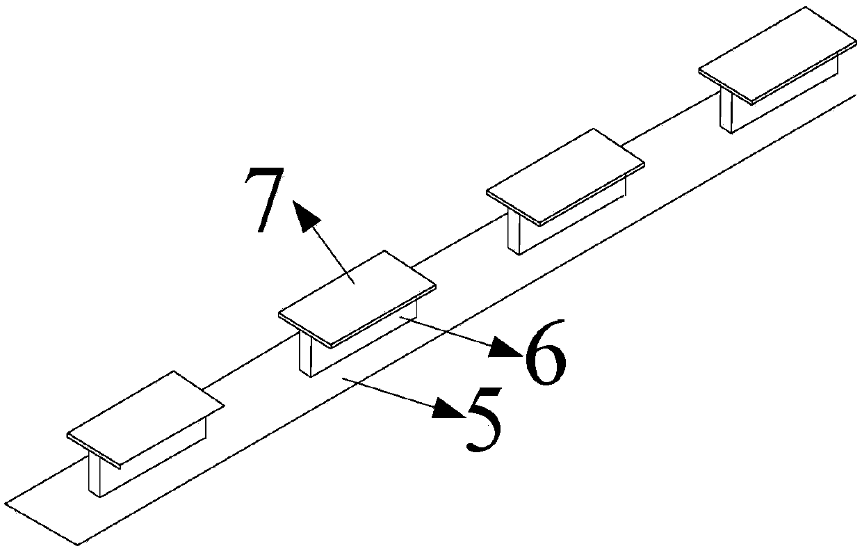
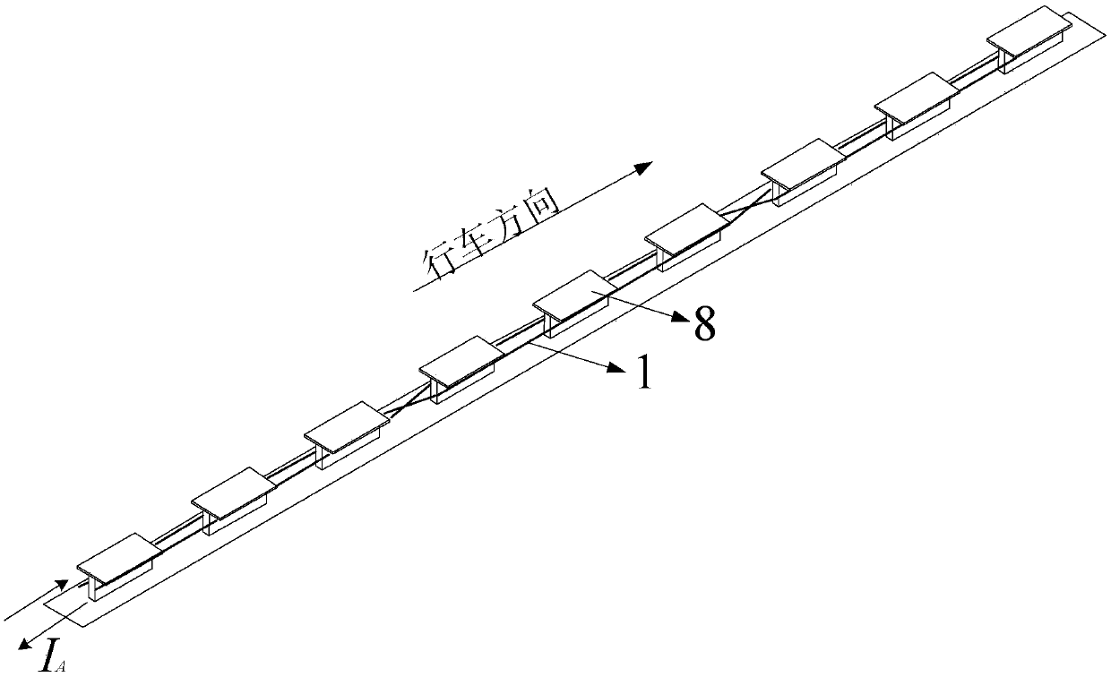
In order to overcome the problems of large output power fluctuation, short transmission distance and poor electromagnetic compatibility in an existing wireless power supply magnetic coupling mechanism, the invention provides a three-phase type magnetic coupling mechanism applied to dynamic wireless power supply of vehicles, and belongs to the technical field of wireless power energy transmission.The three-phase type magnetic coupling mechanism comprises a power supply track used for transmitting power energy and a power energy receiving device; the power supply track is mounted below a road in the travelling direction of a vehicle and comprises three-phase power supply cables and a power supply track magnetic core, and the three-phase power supply cables are wound around the power supplytrack magnetic core; the three-phase power supply cables generate a magnetic field after being energized and transmit the power energy to the power energy receiving device; the matching mode of the three-phase cables and the power supply track magnetic core is cross winding or sequential winding; the rest of the three-phase power supply cables is same except that the space positions of the three-phase power supply cables in the vehicle travelling direction have difference of a one-third vehicle travelling cycle distance in the space position, and the power energy receiving device is mounted ona vehicle chassis, voltage is generated through a electromagnetic induction principle to supply power to a load, and wireless transmission of the power energy is achieved.

Description

Technical field [0001] The invention belongs to the technical field of wireless power transmission, and in particular relates to a three-phase magnetic coupling mechanism applied to dynamic wireless power supply of vehicles. Background technique [0002] Due to the constraints of low battery energy density, inconvenient charging, poor plug-in charging method safety, and many other problems, the speed of development and promotion of electric vehicles is slow. The dynamic wireless power supply technology not only solves the above problems well, but also frees electric vehicles from the shackles of parking and charging, and solves the bottleneck problem of insufficient cruising range. [0003] At present, the rail-type wireless electromagnetic coupling mechanism with magnetic core structure is widely used in vehicle dynamic wireless power supply system due to its good coupling performance and high transmission power. Many magnetic coupling mechanisms with different structures have bee...

Claims


Application Information

Patent Timeline
Patent Type & Authority Applications(China)
IPC IPC(8): B60L11/18H02J50/10H02J50/70
CPCB60L53/12H02J50/10H02J50/70Y02T10/70Y02T10/7072Y02T90/14
Inventor 崔淑梅宋贝贝高鑫朱春波
Owner HARBIN INST OF TECH
Why Eureka
Try Eureka