

Inchworm-imitating climbing robot suitable for truss structure
A truss structure and robot technology, which is applied in the field of bionic robots, can solve the problems of difficult replacement of ropes, low safety, and high project cost
- Summary
- Abstract
- Description
- Claims
- Application Information
AI Technical Summary
Problems solved by technology
Method used
Image

Examples
Embodiment 1
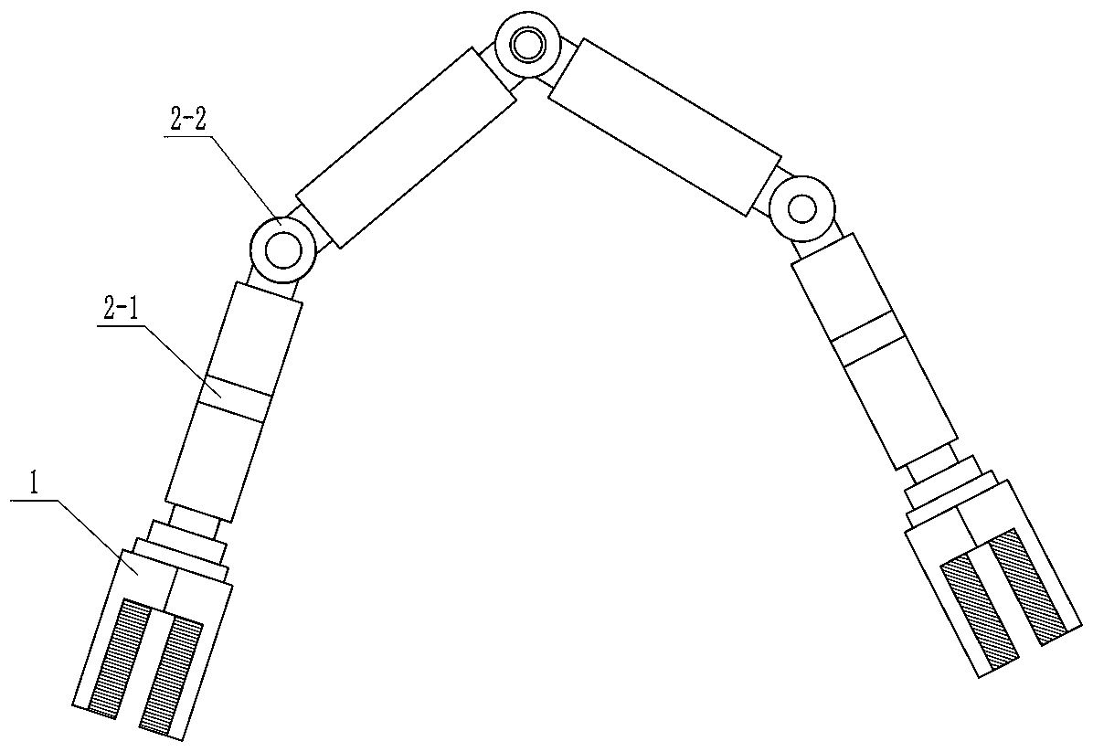
[0031] Such as image 3 and Figure 4 As shown, an inchworm-like climbing robot suitable for a truss structure includes gripper modules 1 at both ends, several joint modules 2 connected in series between the two gripper modules 1, a processor, a dual A target image acquisition module, an image processing module and a path calculation module;
[0032] Several joint modules 2 include an I-type joint module 2-1 and a T-type joint module 2-2, each joint module is driven by a steering gear, and two adjacent joint modules are fixedly connected, wherein the I-type joint module Refers to the joint that can rotate along its own axis, mainly used to realize the twisting and turning of the joint. The T-joint module refers to the joint whose rotation axis is perpendicular to its own axis, and is mainly used to realize the swing of the joint. The two joint modules are The conventional joints of the inchworm-like climbing robot are not described in detail.
[0033] The two cameras of the...
Embodiment 2
[0040] Such as Figure 5 and Figure 6 As shown, the clamper module includes a module body 6, a clamping claw, a first rotating part 3, a second rotating part 4 and a third rotating part 5, and the clamping claw includes three claws 7-1, 7-2 and 7-3, wherein two claws 7-1 and 7-2 are hinged on one side of the module body 6, and the third claw 7-3 is hinged on the other side of the module body 6 and is located In the middle position of the other two claws 7-1 and 7-2, the three claws can be folded inward to form a clamping space, and the three claws are driven to rotate by the same steering gear. The module main body 6 horizontally rotates the matching rotary disk, the second rotating part 4 is mounted on the rotary disk, the third rotating part 5 is mounted on the second rotating part, and the rotating shafts of the three rotating parts are respectively two The two vertical and three rotating parts are all driven by matching servos.
PUM
 Abstract
Description
Claims
Application Information