Eureka AIR delivers breakthrough ideas for toughest innovation challenges, trusted by R&D personnel around the world.

Silencing mechanism for loading machine

A loader and noise reduction technology, which is applied in the direction of noise reduction devices, machines/engines, exhaust devices, etc., can solve problems such as poor noise reduction effect, small buffering effect, and large loader power, so as to reduce noise and reduce energy transfer.

Active Publication Date: 2018-08-10
峡江县飞福科技有限公司
View PDF22 Cites 1 Cited by
  • Summary
  • Abstract
  • Description
  • Claims
  • Application Information

AI Technical Summary

Problems solved by technology

[0002] The loader is noisy during work. Installing a muffler is a conventional means to overcome noise pollution. The existing technology is to install the muffler as an independent accessory near the engine and connect the engine with the muffler. The current traditional muffler works The pulse airflow generated when passing through the intake and exhaust chambers expands and contracts twice, and the airflow speed is buffered, so that the frequency of the sound wave changes, thereby reducing the noise and realizing the function of noise reduction. However, the power of the loader is large, and the current noise reduction The device has little buffering effect on the pulsed airflow generated by the exhaust of the engine, and the back pressure is large when exhausting, and the noise reduction effect is poor.

Method used


Image

  • Silencing mechanism for loading machine
  • Silencing mechanism for loading machine
  • Silencing mechanism for loading machine

Examples


Embodiment Construction

[0016] The following will clearly and completely describe the technical solutions in the embodiments of the present invention with reference to the accompanying drawings in the embodiments of the present invention. Obviously, the described embodiments are only some, not all, embodiments of the present invention. Based on the embodiments of the present invention, all other embodiments obtained by persons of ordinary skill in the art without making creative efforts belong to the protection scope of the present invention.

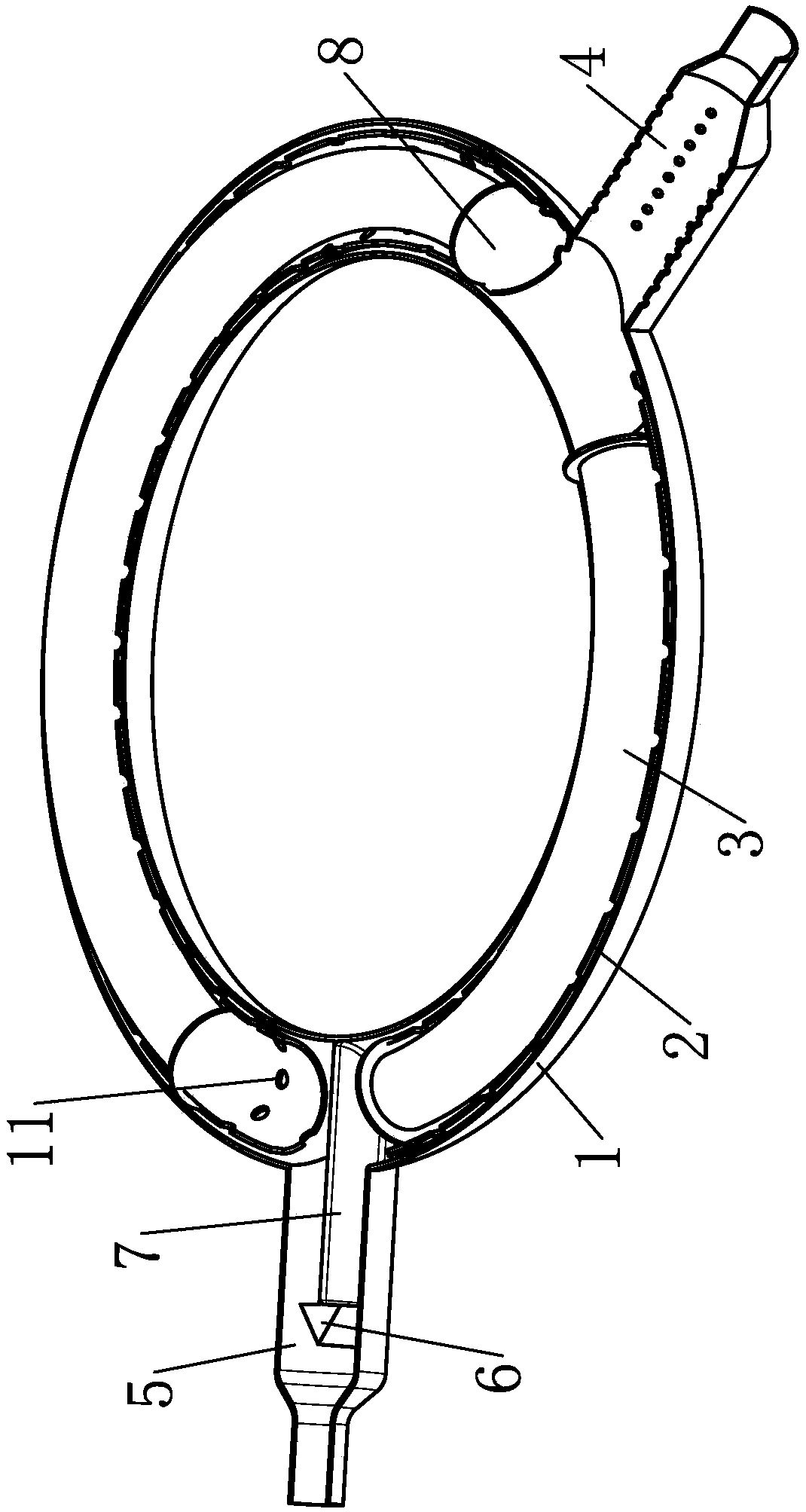
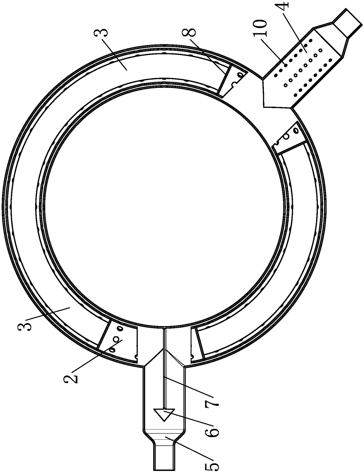
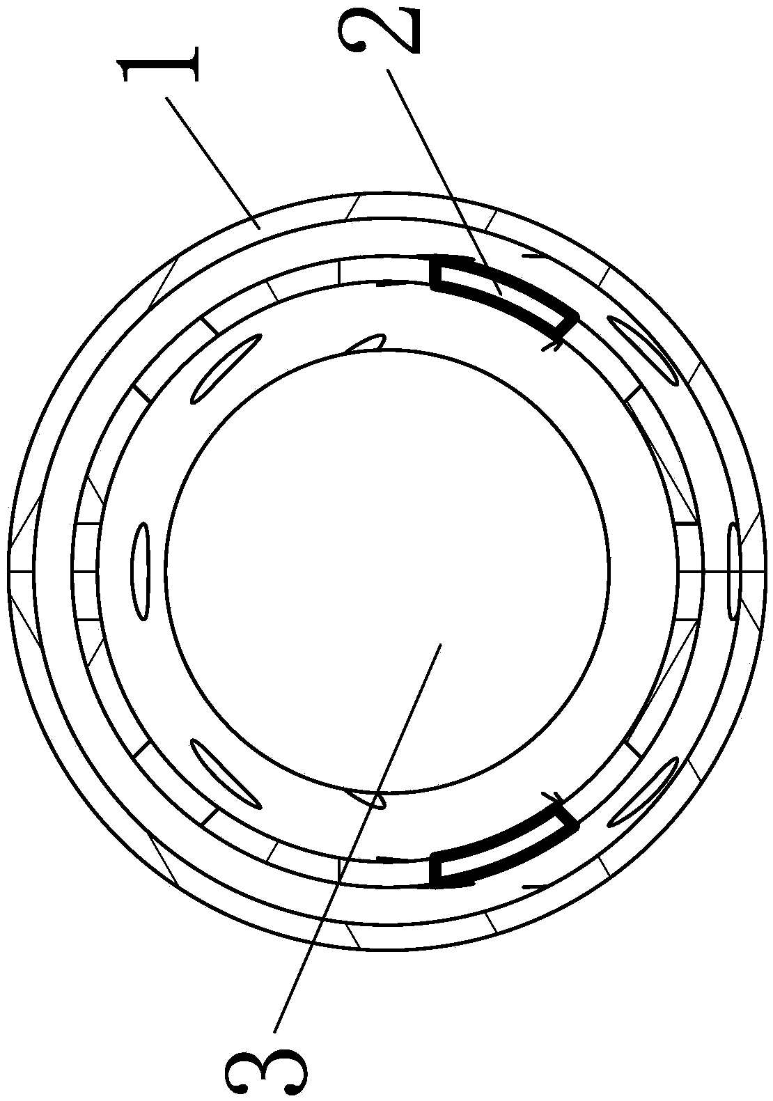
[0017] see Figure 1-4 , the present invention provides a technical solution: a noise reduction mechanism for a loader, including a noise reduction housing 1, the noise reduction housing 1 is a circular pipe, and two openings are arranged outside the noise reduction housing 1, and the two openings of the noise reduction housing 1 are respectively provided with The exhaust pipe 4 and the intake pipe 5 are fixed with a diverter block 6 inside the intake pipe 5 t...


PUM


Abstract

The invention discloses a silencing mechanism for a loading machine. The silencing mechanism comprises a silencing outer cover. The silencing outer cover is a circular pipeline. Two openings are formed in the outer portion of the silencing outer cover. An exhaust pipe and an air inlet pipe are correspondingly arranged on two openings of the silencing outer cover. A splitting block is fixedly arranged inside the air inlet pipe. A splitting plate is arranged at the rear end of the splitting block. The splitting plate is fixedly connected with the inner wall of the silencing outer cover. A soundabsorption net is arranged inside the silencing outer cover. Sound absorption holes are evenly formed in the surface of the sound absorption net. The sound absorption net is fixedly installed with thesilencing outer cover through a bracket. Sound absorption plates are correspondingly arranged at an inlet and an outlet of the sound absorption net. A sound absorption pipe is arranged in the sound absorption net. The sound absorption pipe and the sound absorption net are fixed installed through a support. Air vents are evenly formed in the outer side of the sound absorption pipe. The silencing mechanism can split the gas flow, the exhaust back pressure can be reduced, and meanwhile silencing is carried out through sound interference.

Description

technical field [0001] The invention relates to the technical field of sound-absorbing equipment, in particular to a sound-absorbing mechanism for a loader. Background technique [0002] The loader is noisy during work. Installing a muffler is a conventional means to overcome noise pollution. The existing technology is to install the muffler as an independent accessory near the engine and connect the engine with the muffler. The current traditional muffler works The pulse airflow generated when passing through the intake and exhaust chambers expands and contracts twice, and the airflow speed is buffered, so that the frequency of the sound wave changes, thereby reducing the noise and realizing the function of noise reduction. However, the power of the loader is large, and the current noise reduction The device has little buffering effect on the pulsed air flow generated by the exhaust of the engine, and the back pressure is large when exhausting, and the noise reduction effec...

Claims


Application Information

Patent Timeline
Patent Type & Authority Applications(China)
IPC IPC(8): F01N1/10F01N1/08F01N1/06
CPCF01N1/06F01N1/082F01N1/10F01N2590/08
Inventor 罗燕美
Owner 峡江县飞福科技有限公司
Why Eureka
Eureka Blog
Learn More