Detection device for building material insulation test

A technology for temperature testing and building materials, applied in the field of building materials, can solve problems such as inability to eliminate environmental impact, loss of heat flow, large heat transfer coefficient, etc., and achieve the effects of saving maintenance and care time, increasing service life, and improving work efficiency

Inactive Publication Date: 2018-08-10
温州广信工程监理有限公司
View PDF1 Cites 1 Cited by
  • Summary
  • Abstract
  • Description
  • Claims
  • Application Information

AI Technical Summary

Problems solved by technology

[0002] The on-site detection technology of the heat transfer coefficient of the enclosure structure is mainly the heat flow meter method. The heat flow meter method requires that the temperature difference between the inner and outer surfaces of the maintenance structure should not be less than 10K (about 10 degrees Celsius), and the indoor temperature should be kept stable. ) is generally difficult to meet this requirement. Now many testing equipment adopt the heat flow meter method. In order to meet the requirement that the temperature difference between the inner and outer surfaces should not be less than 10K (about 10 degrees Celsius), the heat flow meter is placed in the environmental heat box, but the indoor temperature cannot be kept stable. , cannot eliminate the influence of the overall indoor environment, ignoring the significant impact of the resulting heat loss on the edge of the wall and the heat loss of the box on the test data, the heat flow in the box has a certain loss, resulting in a small thermal resistance If the temperature is too large, the heat loss at the edge of the equipment and the heat loss of the box will have a significant impact on the test data. For the same wall, use a field-maintenance structural heat transfer coefficient meter (1.2m side length of a single-layer structure box) and a protective heat Compared with the plate method, the result is about 15% larger than that. Using a commercially available on-site maintenance structure heat transfer coefficient meter (1.0m side length single-layer structure box) to compare with the protective hot plate method, the result is about 28% larger. At present, there is no equipment that can effectively eliminate the heat loss of the edge and the heat loss of the box. In the prior art, for example, the invention patent with the application number 201720960188.3 includes the environmental box, the detection box, the first heater and the second heater. , the detection box is located inside the environmental box, a first temperature sensor is provided between the environmental box and the detection box, a second temperature sensor is provided in the detection box, and the first heater is located between the environmental box and the detection box. Between the boxes, the second heater is arranged in the detection box, the first temperature sensor sends a temperature detection signal to the first heater, and the second temperature sensor sends a temperature detection signal to the second heater. Although the invention has a simple structure, But there are many deficiencies and defects. In the existing equipment, the design of the first heater has defects. When in use, the connection between the first heater and the second heater and the environmental box is unstable. When in use, the first heater The first heater and the second heater are prone to shaking, which reduces the service life of the first heater and the second heater while increasing the cost of use, causing inconvenience to the maintenance staff, increasing the working pressure of the maintenance personnel, and making maintenance Personnel are prone to physical fatigue, and the positions of the first heat dissipation plate and the second heat dissipation plate are not conducive to the heat dissipation of the temperature inside the environmental box, which affects the detection results. In view of these situations, in order to avoid the above technical problems, it is necessary to provide a method for The detection device of building material insulation temperature test to overcome the defects in the prior art

Method used


Image

  • Detection device for building material insulation test
  • Detection device for building material insulation test
  • Detection device for building material insulation test

Examples


Embodiment Construction

[0014] The following will clearly and completely describe the technical solutions in the embodiments of the present invention with reference to the accompanying drawings in the embodiments of the present invention. Obviously, the described embodiments are only some, not all, embodiments of the present invention. Based on the embodiments of the present invention, all other embodiments obtained by persons of ordinary skill in the art without making creative efforts belong to the protection scope of the present invention.

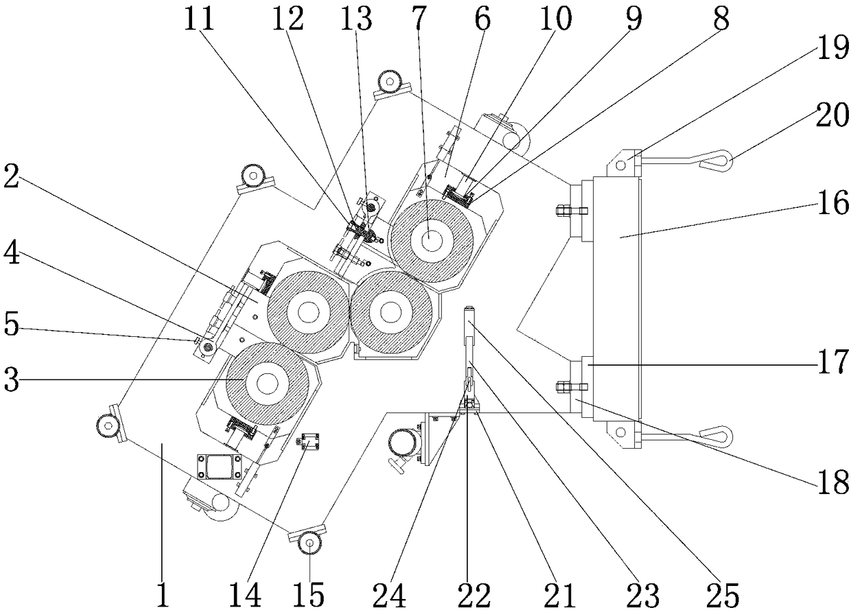
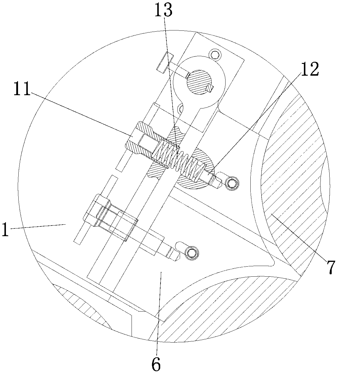
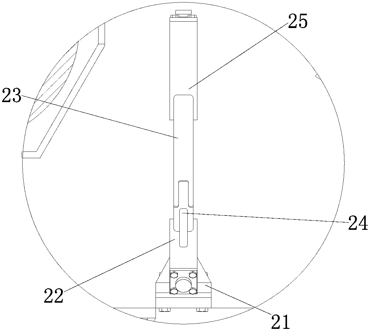
[0015] see Figure 1-3, the present invention provides a technical solution: a detection device for building material temperature preservation test, including a box body 1 for installing the first bracket 2 and the second bracket 6, the right outer wall of the box body 1 and the bottom plate 17 A spacer 18 is installed at the junction of the left outer wall to connect and fix the box body 1 and the base 16. The left side outer wall of the spacer 18 is connecte...


PUM


Abstract

The invention discloses a detection device for a building material insulation test. The detection device comprises a box, a bottom plate is mounted on the right outer wall of the box, the left outer wall of the bottom plate is connected with the right outer wall of the box, a base is mounted on the right outer wall of the bottom plate, the left outer wall of the base is connected with the right outer wall of the bottom plate, side plates are mounted at the upper end and the lower end of the base, and the inner walls of the side plates are connected with the outer wall of the base. According tothe detection device for the building material insulation test, by coordination of the bottom plate, the base and the side plates, the bottom plate, the base and the box are more firmly connected under the action of hooked reinforcing steel bars, good supporting conditions are provided for fixed connection of a first support and a second support with the box, the first support and the second support can be fixed into the box under the action of a pull rod and a pin, and the detection device is suitable for popularization and use.

Description

technical field [0001] The invention relates to the technical field of building materials, in particular to a detection device for a temperature holding test of building materials. Background technique [0002] The on-site detection technology of the heat transfer coefficient of the enclosure structure is mainly the heat flow meter method. The heat flow meter method requires that the temperature difference between the inner and outer surfaces of the maintenance structure should not be less than 10K (about 10 degrees Celsius), and the indoor temperature should be kept stable. ) is generally difficult to meet this requirement. Now many testing equipment adopt the heat flow meter method. In order to meet the requirement that the temperature difference between the inner and outer surfaces should not be less than 10K (about 10 degrees Celsius), the heat flow meter is placed in the environmental heat box, but the indoor temperature cannot be kept stable. , cannot eliminate the inf...

Claims


Application Information

Patent Timeline
Patent Type & Authority Applications(China)
IPC IPC(8): G01N25/20G01N25/18
CPCG01N25/20G01N25/18
Inventor 陈华育
Owner 温州广信工程监理有限公司
Why Eureka
Try Eureka