Bilateral dielectric rod clamping dual-electron-beam periodic zigzag metal wire slow-wave structure

A technology of slow wave structure and double electron injection, which is applied to the circuit components of transit-time electron tubes, can solve the problems of low output power, weak electric field, low coupling impedance, etc., achieve high output power and enhance interaction strength and the effect of output power

Active Publication Date: 2018-08-10
UNIV OF ELECTRONICS SCI & TECH OF CHINA
View PDF4 Cites 6 Cited by
  • Summary
  • Abstract
  • Description
  • Claims
  • Application Information

AI Technical Summary

Problems solved by technology

[0004] The object of the present invention is: the present invention provides a slow-wave structure of double-electron injection periodic meander metal wires clamped by dielectric rods on both sides, which solves the problem that the distance between adjacent meander lines in the existing angle-logarithmic metal wire slow-wave structure will vary with the slow The change of the length of the wave structure leads to the weakening of the electric field between adjacent meander lines, resulting in low coupling impedance and low output power

Method used


Image

  • Bilateral dielectric rod clamping dual-electron-beam periodic zigzag metal wire slow-wave structure
  • Bilateral dielectric rod clamping dual-electron-beam periodic zigzag metal wire slow-wave structure
  • Bilateral dielectric rod clamping dual-electron-beam periodic zigzag metal wire slow-wave structure

Examples


Embodiment 1

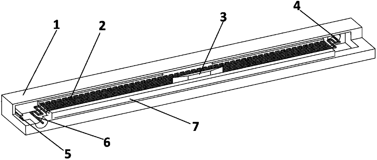
[0029] A slow-wave structure of double-electron injection periodic meandering metal wires clamped by dielectric rods on both sides, including a metal cavity 1, a cathode electron emitter 5 welded at one end of the metal cavity 1, and a slow-wave structure arranged on the metal cavity 1 The main body, the slow wave structure The main body includes a metal wire 2, a dielectric rod 7 arranged on both sides of the metal wire 2 for fixing, and an attenuator 3 arranged in the middle of the dielectric rod 7. A transition section is provided at both ends of the metal wire 2, and the transition section and the The metal cavity 2 is internally connected and forms a coaxial interface to the outside. The metal wire 2 adopts a uniform periodic meandering metal wire, and the metal wire 2 is connected end to end in a "several" shape.

[0030] Working principle: Dielectric rods 7 are used on both sides to support the slow-wave structure body, and a cathode electron emitter 5 is provided at one...

Embodiment 2

[0032] The cross section of the metal wire 2 is square, the side length w of the cross section is 0.07 mm, the lateral width h of a single period is 1.3 mm, and the distance wt between parallel segments of the metal wire 2 is 0.13 mm. The cross section of the dielectric rod 7 is "convex" shape, the total length d of the dielectric rod 7 is 20mm, and the lengths of each side are d1=0.3mm, d2=0.4mm, d3=0.38mm, d4=0.7mm. The cathode electron emitter 5 has a lateral dimension of 1.3 mm and a thickness of 0.07 mm. The transition section includes an input transition section 6 and an output transition section 4 that are reversely symmetrical, and its transverse heights are successively h=1.3mm, h1=1mm and h2=0.65mm, and its width is successively w4=0.145, w3= 0.152, w2=0.16 and w1=0.162. The cross section of the attenuator 3 is a standard trapezoid, the length of the upper side and the lower side are respectively S1=2mm and S2=3.6mm, and the height is S3=3.1mm.

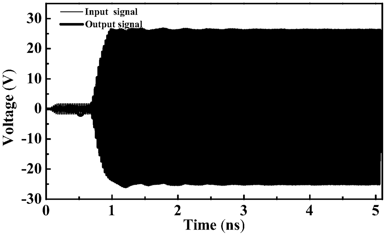
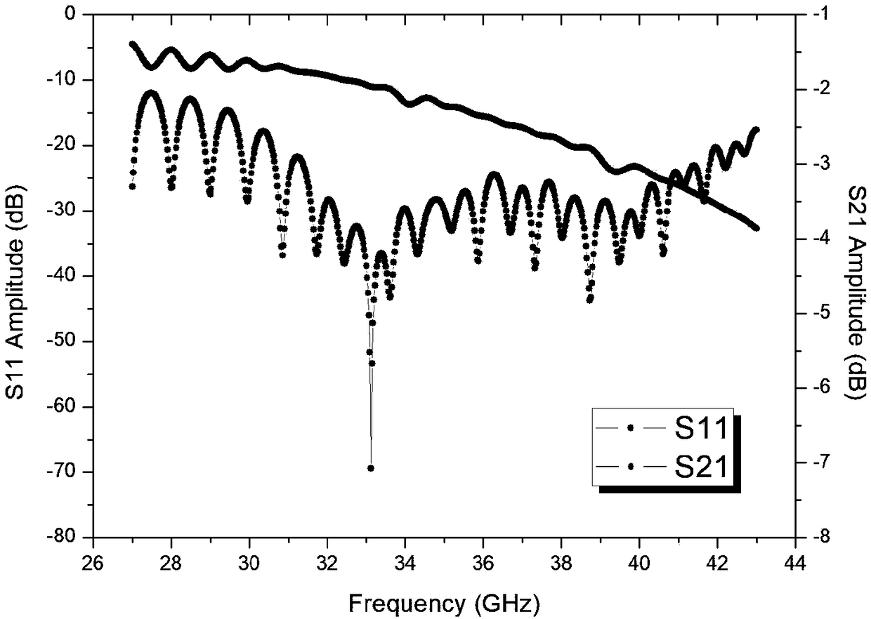
[0033] Effect anal...


PUM

PropertyMeasurementUnit
widthaaaaaaaaaa
lengthaaaaaaaaaa
sizeaaaaaaaaaa

Abstract

The invention discloses a bilateral dielectric rod clamping dual-electron-beam periodic zigzag metal wire slow-wave structure, and relates to the field of a planar traveling wave tube slow-wave structure. The bilateral dielectric rod clamping dual-electron-beam periodic zigzag metal wire slow-wave structure comprises a metal cavity, a cathode electron emitter welded at one end of the metal cavityand a slow-wave structure body arranged on the metal cavity, the slow-wave structure body comprises a metal wire, dielectric rods arranged at two sides of the metal wire respectively for fixation andan attenuator arranged at the middle of the dielectric rods, both ends of the metal wire are provided with a gradually changing section, each gradually changing section is communicated with the internal part of the metal cavity and externally forms a coaxial interface, the metal wire adopts a uniformly periodic zigzag metal wire, and the metal wire is connected end to end in a in a shape like a Chinese character 'ji'. The bilateral dielectric rod clamping dual-electron-beam periodic zigzag metal wire slow-wave structure solves a problem that the existing angular logarithmic metal wire slow-wave structure is low in coupling impedance and low in output power because the spacing between the adjacent zigzag wires changes along with the length of the slow-wave structure and the electric field between adjacent zigzag wires is weakened, and achieves an effect of improving the coupling impedance and output power of the slow-wave structure.

Description

technical field [0001] The invention relates to the field of slow-wave structures of planar traveling wave tubes, in particular to a slow-wave structure of double-electron injection periodic meander metal wires clamped by dielectric rods on both sides. Background technique [0002] With the rapid development of the information age, especially the coming of the 5G era, there is a great demand in the industry for electronic devices that can generate high-power and high-frequency electromagnetic wave signals. Although electric vacuum devices represented by traditional traveling wave tubes and klystrons can meet the above requirements, their excessive structural size and required high voltage (usually reaching tens of kilovolts) cannot There are still many problems; therefore, a new type of planar traveling wave tube device emerges as the times require, and its core part is a slow wave interaction system designed with a microstrip line structure; using mature microstrip line tec...

Claims


Application Information

Patent Timeline
Patent Type & Authority Applications(China)
IPC IPC(8): H01J23/24H01J23/30
CPCH01J23/24H01J23/30
Inventor 王禾欣许多师凝洁李新义何腾龙宫玉彬段兆云巩华荣王战亮路志刚
Owner UNIV OF ELECTRONICS SCI & TECH OF CHINA
Why Eureka
Try Eureka