motor

A motor and stator iron core technology, applied in the field of motors, can solve the problems of increasing efficiency, reducing coiling workability, reducing filling factor, etc., and achieving the effects of reducing copper loss, increasing efficiency, and saving manufacturing costs

Active Publication Date: 2020-12-04
LG ELECTRONICS INC
View PDF4 Cites 0 Cited by
  • Summary
  • Abstract
  • Description
  • Claims
  • Application Information

AI Technical Summary

Problems solved by technology

Therefore, the copper loss generated in the coil itself is relatively large, and thus, it is very difficult to increase the efficiency
[0019] In addition, since the coil needs to be wound using a nozzle, the fill factor can only be reduced, and the coiling workability is inevitably reduced.
[0020] Also, it is difficult to change the shape and size of the stator core, so there is a limit to reducing the amount of materials used to form the stator core.
Therefore, in the prior art, only small changes can be made to the shape or size of the stator core itself, and it is very difficult to significantly reduce the amount of materials used in the stator core.

Method used


Image

  • motor
  • motor
  • motor

Examples


Embodiment Construction

[0076] Hereinafter, preferred embodiments of the present invention will be described in detail with reference to the accompanying drawings.

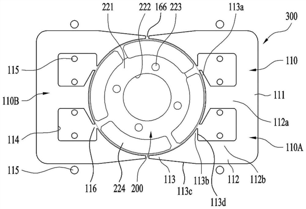
[0077] figure 2 A schematic plan view of a motor according to an embodiment of the present invention is shown.

[0078] The motor 300 may be composed of a stator 100 and a rotor 200 .

[0079] The stator 100 may include a stator core 110 formed of a magnetic body, and the rotor 200 may include a rotor core 221 formed of a magnetic body.

[0080] The stator core 110 and the rotor core 221 form a path through which magnetic flux moves, and may be formed by laminating electrical steel sheets in order to reduce core copper loss.

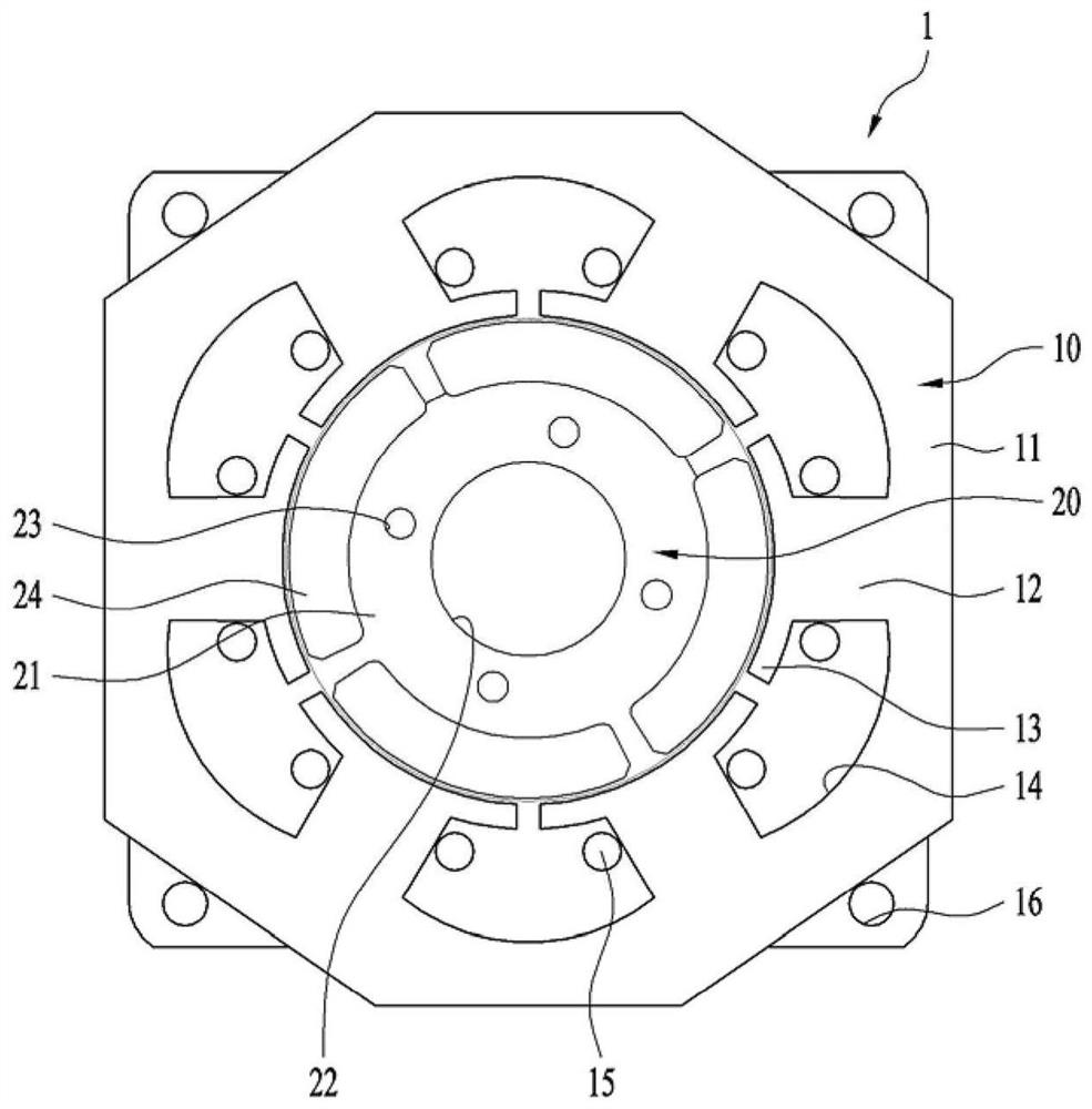
[0081] A shaft hole 222 and a coupling hole 223 may be formed in the rotor core 221 , and a plurality of permanent magnets 224 may be provided. therefore, figure 2 The rotor shown can be used with figure 1 The rotors shown are the same. However, as described below, various types of rotors can be applied to ...


PUM


Abstract

The invention relates to a motor, in particular to a motor with excellent performance and low manufacturing cost. According to an embodiment of the present invention, a motor including a stator core is provided, and the stator core includes a first stator core and a second stator core, which are provided separately from the first stator core and Formed to be bilaterally symmetrical with the first stator core, the first stator core and the second stator core include: a yoke; extending in a central direction; and outer corner teeth extending from upper and lower ends of the yoke respectively longer than the length of the central teeth.

Description

technical field [0001] The invention relates to a motor, in particular to a motor with excellent performance and low manufacturing cost. Background technique [0002] Typically, a motor transmits the rotational force of a rotor to a shaft, thereby causing the shaft to drive a load. For example, the rotating shaft may be connected to a drum of a washing machine to drive the drum, and the rotating shaft may be connected to a fan of a refrigerator to thereby drive the fan to supply cool air to a desired space. In addition, in the compressor, a motor is also used for compressing the refrigerant. [0003] In addition, in such a motor, the rotor rotates by electromagnetic interaction with the stator. For this purpose, a coil is wound around the stator, and the rotor rotates relative to the stator as a current is applied to the coil. [0004] The stator is composed of a stator core composed of conductors. In addition, the stator is usually a structure fixed to an object. There...

Claims


Application Information

Patent Timeline
Patent Type & Authority Patents(China)
IPC IPC(8): H02K1/14H02K1/27
CPCH02K1/148H02K1/276H02K2201/03H02K2213/03H02K1/14H02K3/524H02K21/14H02K21/22H02K1/143H02K1/146H02K1/165H02K15/024H02K16/04
Inventor 金宰浩甘炳国朴治晟安址限
Owner LG ELECTRONICS INC
Why Eureka
Try Eureka