A zero voltage switch boost circuit and its control method

A zero-voltage switching, current detection circuit technology, applied in control/regulation systems, high-efficiency power electronic conversion, electrical components, etc., can solve problems such as large switching loss and reverse recovery, and achieve high light-load efficiency, simple application, Achieve the effect of light-load frequency reduction

Active Publication Date: 2020-07-17
MORNSUN GUANGZHOU SCI & TECH
View PDF5 Cites 0 Cited by
  • Summary
  • Abstract
  • Description
  • Claims
  • Application Information

AI Technical Summary

Problems solved by technology

[0007] In view of this, the present invention provides a Boost circuit of zero-voltage switching and its control method to solve the problem of excessive switching loss in high-frequency operation, solve the reverse recovery problem existing in the continuous rectification diode of the inductor current, and also solve the problem of hard switching The resulting EMI problem

Method used


Image

  • A zero voltage switch boost circuit and its control method
  • A zero voltage switch boost circuit and its control method
  • A zero voltage switch boost circuit and its control method

Examples


no. 1 example

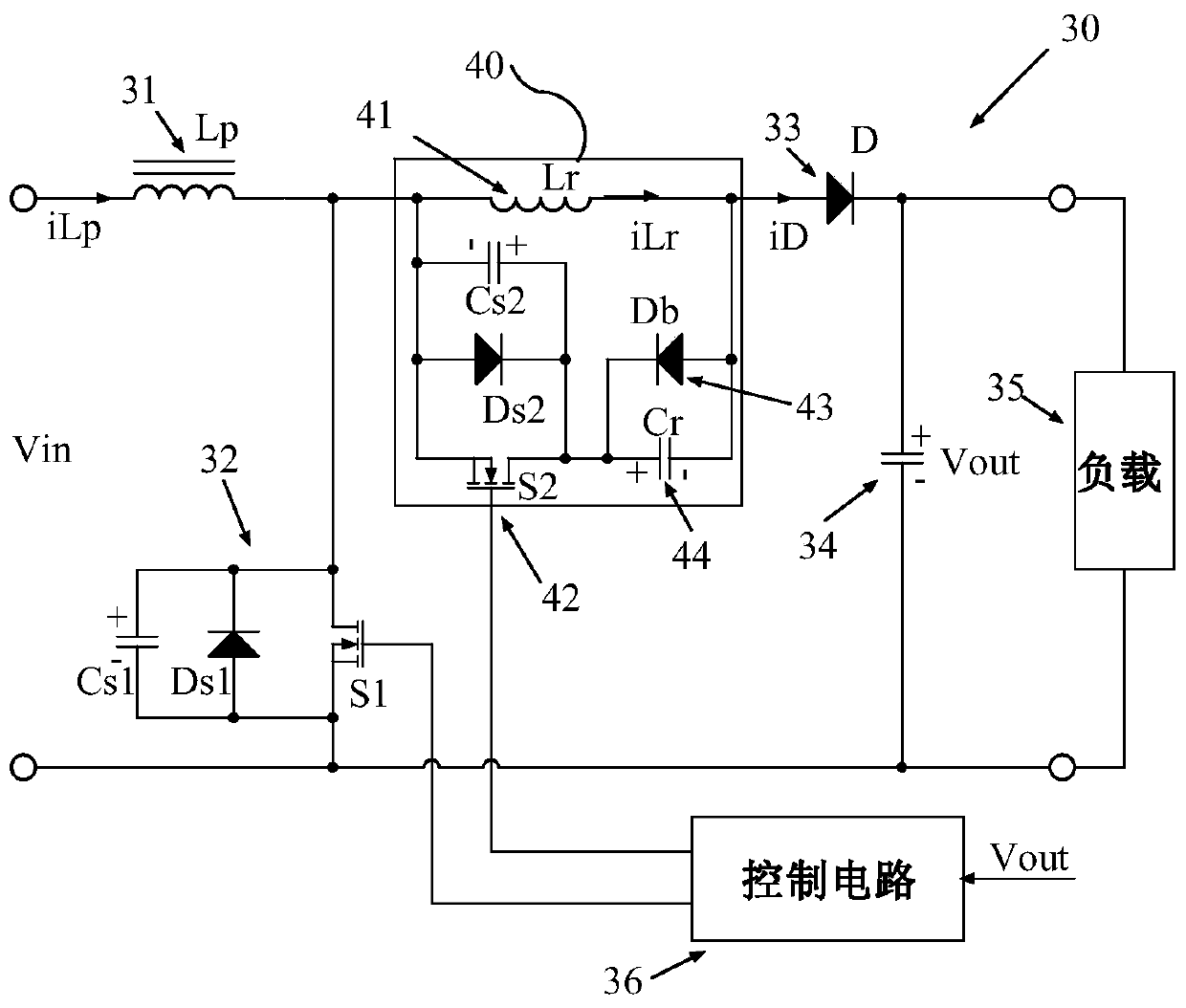
[0044] image 3 Shown is a schematic diagram 30 of the first embodiment of the zero voltage switch Boost circuit according to the present invention, similar to the traditional Boost circuit, the zero voltage switch Boost circuit 30 includes a boost inductor 31, a main switch tube 32, a rectifier diode 33, an output filter The capacitor 34 and the control circuit 36 ​​output the output voltage Vout at both ends of the filter capacitor 34 to supply power to the load 35; the control circuit 36 ​​generates a feedback voltage signal according to the output voltage Vout and adjusts the duty cycle of the main switching tube 32 according to the feedback voltage signal; One end of the boost inductor 31 is connected to the input voltage +, the other end of the boost inductor 31 is connected to the drain of the main switching tube 32, the source of the main switching tube 32 is connected to the input voltage -, and the gate of the main switching tube 32 is connected to the control circuit...

no. 2 example

[0064] Figure 8-1 The schematic diagram and control block diagram of the second embodiment of the present invention are shown. The difference from the first embodiment is that a CS current detection circuit is added between the source of the main switch 32 and the control circuit.

[0065] This embodiment is mainly embodied in the light load control, sampling the output voltage Vout to control the stability of the output voltage, and sampling the peak current of the main switching tube to realize the light load control. When the load decreases, the peak current of the main switching tube decreases, and when the load decreases to a certain extent, the circuit enters the DCM mode to work. When the peak current decreases to a certain level, keep the minimum peak current from the control and no longer decrease, that is, the minimum peak current control, that is to say, when the load continues to decrease, the output of the converter is stabilized by reducing the operating frequen...

no. 3 example

[0067] Figure 9It shows the principle diagram according to the third embodiment of the present invention, that is to say, the zero-voltage switching circuit 40 of the present invention is also applicable to the Boost circuit of synchronous rectification, and the difference from Embodiment 1 is that the rectifier diode 33 is replaced by synchronous rectification Switch tube 81, the input terminal of the zero voltage switching circuit 40 is connected to the drain of the main switch tube 32, the output terminal is connected to the source of the synchronous rectification switch tube 81, and the drain of the synchronous rectification switch tube 81 is connected to the output filter capacitor 34 positive. In addition, this embodiment also includes a control circuit 86. The control circuit 86 outputs three-way driving signals to control the switching of the main switching tube 32, the auxiliary switching tube 42, and the synchronous rectification switching tube 81, wherein the main ...


PUM


Abstract

The present invention provides a Boost circuit of a zero-voltage switch and a control method thereof. An auxiliary resonant circuit is connected in series in a rectifier circuit of a main power circuit. Zero-voltage conduction, and then use the resonance between the resonant capacitor and the resonant inductor to realize the rapid increase of the resonant inductor current and make the current of the resonant inductor larger than the current of the Boost boost inductor, and use the diode connected in parallel with the resonant capacitor to resonant inductor current. , to ensure that the voltage of the resonant capacitor will not reverse and the current of the resonant inductor will not decrease rapidly after reaching the maximum value. When the auxiliary switching tube is turned off, the difference between the resonant current and the boost inductor current is used to realize the zero-voltage turn-on of the main switching tube.

Description

technical field [0001] The invention relates to power electronic circuits, in particular to a zero-voltage switch Boost circuit and a control method thereof. Background technique [0002] A conventional power supply block diagram such as figure 1 As shown, the bridge rectifier circuit 11 converts the AC input into a DC voltage and supplies it to the Boost converter 20, and the Boost converter provides a power factor correction function to meet industry standards or simply converts a fluctuating voltage to a stable voltage Or a voltage range with a smaller variation range, the DC / DC converter in the subsequent stage converts the output voltage of the Boost converter to the voltage required by the load and realizes the isolation function. Usually, the AC input range is 85-265VAC, and the regulated voltage value of the Boost converter is 400V or the regulated voltage range is 200-400V. The narrower the output voltage range of the front-stage Boost circuit, the simpler the des...

Claims


Application Information

Patent Timeline
Patent Type & Authority Patents(China)
IPC IPC(8): H02M3/158H02M1/088
CPCH02M1/088H02M3/158H02M1/0058H02M3/156H02M1/342Y02B70/10
Inventor 袁源
Owner MORNSUN GUANGZHOU SCI & TECH
Why Eureka
Try Eureka