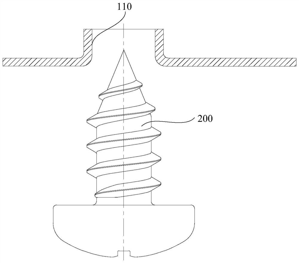
Flange bottom hole structure and electrical housing

A hole structure and flanging technology, which is applied in the field of electrical housings, can solve the problems of poor surface of the film-coated board 102, low production efficiency, easy to be scrapped, etc., and achieve the effects of simple structure, improved production efficiency, and convenient processing and manufacturing.

Active Publication Date: 2021-03-30
WUXI LITTLE SWAN ELECTRIC CO LTD
View PDF5 Cites 0 Cited by
  • Summary
  • Abstract
  • Description
  • Claims
  • Application Information

AI Technical Summary

Problems solved by technology

[0003] related technologies, such as Figure 1 to Figure 3 As shown, after punching and blanking the opening area 104 of the film-coated plate 102, the flanged bottom hole 110 that can be matched with the self-tapping screw 200 is formed, because the flanged bottom hole 110 partially falls off when the punching bursts. , partially remaining, the film 106 is easy to fall off from the base material under the action of high temperature generated by high-speed stamping, and together with the blanking waste 108 of the base material, randomly adheres to the surface of the film-coated board 102, causing the parts to be easily crushed in the subsequent process , so it is easy to cause surface defects of the film-coated board 102
Due to the existence of more flanging and bottom holes 110 on the film-coated board 102 used in the above-mentioned household appliances, there are problems such as high scrap rate and low production efficiency in actual production, especially in the field of electrical appliance housings, due to the There are a large number of flanging bottom holes 110 on the casing box (ie, the film-coated board 102), which makes the box of the electrical appliance casing easy to be scrapped during processing and manufacturing.

Method used


Image

  • Flange bottom hole structure and electrical housing
  • Flange bottom hole structure and electrical housing
  • Flange bottom hole structure and electrical housing

Examples


Embodiment Construction

[0050] In order to understand the above-mentioned purpose, features and advantages of the present invention more clearly, the present invention will be further described in detail below in conjunction with the accompanying drawings and specific embodiments. It should be noted that, in the case of no conflict, the embodiments of the present application and the features in the embodiments can be combined with each other.

[0051] In the following description, many specific details are set forth in order to fully understand the present invention, but the present invention can also be implemented in other ways different from those described here, therefore, the protection scope of the present invention is not limited to the specific details disclosed below. EXAMPLE LIMITATIONS.

[0052] Refer below Figure 4 to Figure 7 The flanged bottom hole structure and the electrical appliance casing provided according to some embodiments of the present invention are described.

[0053] Suc...


PUM


Abstract

The invention provides a flanging bottom hole structure and an electrical appliance housing, wherein the flanging bottom hole structure includes: a plate body, the opening area of ​​the plate body is bent toward one side of the plate body, forming an opening facing the other side of the plate body And a cavity suitable for the self-tapping screw; wherein the self-tapping screw can be screwed into the cavity from the opening end of the cavity, and can pass through the hole area, so that the hole area is spread around. Through the technical scheme of the present invention, the flanging and bottom hole structure is not easy to produce waste in the process of manufacturing, so that it is not easy to appear bad phenomenon on the surface of the board body, has the advantages of simple structure, convenient processing and manufacturing, and can improve the cooperation with self-tapping screws Tightness and reliability after connection.

Description

technical field [0001] The present invention relates to the field of household electrical appliances, in particular to a flanged bottom hole structure and an electrical appliance housing with the flanged bottom hole structure. Background technique [0002] At present, the existing film-coated panels include VCM (Vinyl chloride monomer, vinyl chloride) steel plates, VCM steel plates use steel plates as the base material, and the film is PVC (Polyvinyl chloride, polyvinyl chloride) layer, PET (Polyethyleneterephthalate, polyparaphenylene) The multi-layer composite board of ethylene glycol diformate) layer and printing layer has the advantages of corrosion resistance, friction resistance, beautiful appearance, gorgeous color, various varieties, low density, etc., and also has the high strength and good plasticity of the steel plate, etc. The advantages of mechanical properties are widely used in household appliances such as refrigerators and electrical shells. [0003] related...

Claims


Application Information

Patent Timeline
Patent Type & Authority Patents(China)
IPC IPC(8): H05K5/04
CPCH05K5/04Y02E60/10
Inventor 齐科锋杨安民慕善明
Owner WUXI LITTLE SWAN ELECTRIC CO LTD
Why Eureka
Try Eureka