Main shaft for large flow electromagnetic valve type injector

A technology of solenoid valves and injectors, which is applied in the direction of fuel injection devices, machines/engines, engine components, etc., can solve the problems affecting the stability and repeatability of the dynamic flow rate of injectors, and the difficulty of effectively increasing the flow rate, so as to improve the dynamic flow rate Stability and repeatability, easy promotion and use, and low cost effects

Pending Publication Date: 2018-08-14
LIUZHOU YUANCHUANG EFI TECH
View PDF0 Cites 0 Cited by
  • Summary
  • Abstract
  • Description
  • Claims
  • Application Information

AI Technical Summary

Problems solved by technology

[0004] The technical problem to be solved by the present invention is to provide a main shaft for a large-flow solenoid valve injector to solve the problems exi

Method used


Image

  • Main shaft for large flow electromagnetic valve type injector
  • Main shaft for large flow electromagnetic valve type injector
  • Main shaft for large flow electromagnetic valve type injector

Examples


Example Embodiment

[0027] Embodiment one:

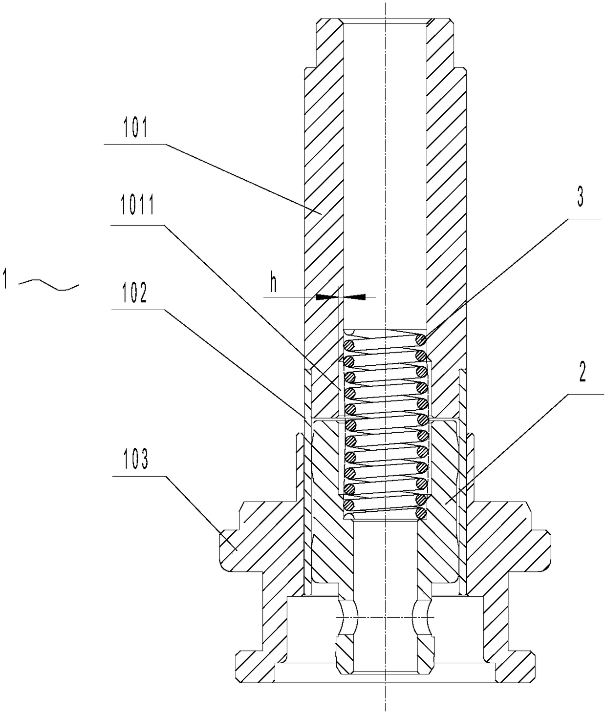
[0028] A spindle for a high flow solenoid injector (see figure 1 ), the main shaft is a split main shaft 1, which includes a main shaft body 101, a magnetic isolation sleeve 102, and an auxiliary shaft 103, wherein:

[0029] The main shaft body 101 is a tubular body structure, the main shaft body 101 is made of low magnetic resistance material, the upper end of the main shaft body 101 is connected with the oil inlet nozzle, the lower end of the main shaft body 101 is connected with the magnetic isolation sleeve 102, the main shaft body 101 A return spring 3 is installed in the center hole, and the center hole wall of the main shaft body 101 is provided with an annular spring relief groove 1011 at the position corresponding to the installation of the return spring 3, and the groove depth of the spring relief groove 1011 is h=0.2mm .

[0030] The magnetic isolation sleeve 102 is made of high magnetic resistance material, the valve core 2 is installed i...


PUM

PropertyMeasurementUnit
Groove depthaaaaaaaaaa

Abstract

The invention discloses a main shaft for a large flow electromagnetic valve type injector and relates to parts of the injector. The main shaft for the large flow electromagnetic valve type injector isa split type main shaft, and comprises a main shaft body, an auxiliary shaft and a magnetism isolating sleeve; the upper end of the main shaft body is connected with an oil inflow nozzle; the lower end of the main shaft body is connected with the magnetism isolating sleeve; the magnetism isolating sleeve is internally provided with a valve element; the periphery of the magnetism isolating sleeveis connected with the auxiliary shaft; a reset spring is installed in a center hole of the main shaft body; the position, corresponding to the reset spring installing position, of the hole wall of thecenter hole of the main shaft body is provided with an annular spring avoiding groove; the main shaft body and the auxiliary shaft are made from a low magnetic resistance material; and the magnetismisolating sleeve is made from a high magnetic resistance material. According to the main shaft for the large flow electromagnetic valve type injector, the magnetic resistance of the magnetism isolating structure can be effectively improved, coupling magnetic flux between the main shaft and the valve element is improved, the electromagnetic force acting on the valve element is increased, and therefore a gap between the valve element and a valve base is increased, and the flow of the injector is effectively increased. According to the main shaft for the large flow electromagnetic valve type injector, the dynamic flow stability of an oil injector can also be improved, the structure is simple, cost is low, and using and popularizing are easy.

Description

technical field [0001] The invention relates to a component of an injector, in particular to a main shaft for a large-flow electromagnetic valve injector. Background technique [0002] Existing solenoid valve injectors used for large flows, such as pen injectors, generally have an integral structure for the main shaft. The main shaft of this integral structure is generally made of low reluctance materials, and the reluctance is low. Therefore, the main shaft and the valve The coupling magnetic flux of the core is small, and the gap between the valve core and the valve seat cannot be increased by increasing the electromagnetic force acting on the valve core, so it is difficult to effectively increase the product flow rate. [0003] In addition, in the existing electromagnetic valve type injector, a return spring is generally installed in the main shaft hole, and the return spring will always bend axially when compressed, resulting in friction between the return spring and the...

Claims


Application Information

Patent Timeline
IPC IPC(8): F02M61/16F02M51/06
CPCF02M51/061F02M61/16F02M61/166
Inventor 唐凤君黎艺文
Owner LIUZHOU YUANCHUANG EFI TECH
Why Eureka
Try Eureka