Balance shaft of three-cylinder engine

A technology of balance shaft and engine, which is applied in the direction of mechanical equipment, vibration suppression adjustment, spring/shock absorber, etc. It can solve the problems of increasing the vibration of the three-cylinder engine, heavy weight, and the cost increase of the engine and the whole vehicle, so as to reduce vibration , the effect of improving comfort

Inactive Publication Date: 2018-08-14
CHERY AUTOMOBILE CO LTD
View PDF9 Cites 9 Cited by
  • Summary
  • Abstract
  • Description
  • Claims
  • Application Information

AI Technical Summary

Problems solved by technology

[0003] Since the working principle of the engine itself is that each cylinder is ignited in sequence at different times to perform external work, and the more cylinders of the four-stroke engine, the more uniform the rotation. Therefore, when the three-cylinder engine is working, the speed unevenness is much larger than that of the four-cylinder engine. During the operation of the three-cylinder engine, the reciprocating motion of the piston and connecting rod assembly will generate a first-order reciprocating moment of inertia, thereby increasing the vibration of the three-cylinder engine
For customers who are accustomed to four-cylinder and above engines, it is difficult to accept the vibration feeling brought by the three-cylinder engine. In order to reduce the vibration of the three-cylinder engine, a balance shaft system is usually added to the engine to balance the piston connecting rod. The reciprocating motion of the assembly generates a first-order reciprocating moment of inertia to reduce the vibration of the three-cylinder engine. However, in order to achieve the effect of balancing the first-order reciprocating moment of inertia generated by the reciprocating motion of the piston-connecting rod assembly, the traditional balance shaft system has a relatively large structure and spatial arrangement. It is complex and heavy, which increases the layout space of the entire engine and the weight of the engine, and brings a significant increase in the cost of the engine and the entire vehicle

Method used


Image

  • Balance shaft of three-cylinder engine
  • Balance shaft of three-cylinder engine
  • Balance shaft of three-cylinder engine

Examples


Embodiment Construction

[0011] combined with Figure 1~4 The present invention will be described in detail.

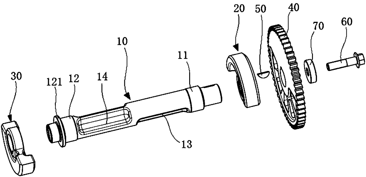
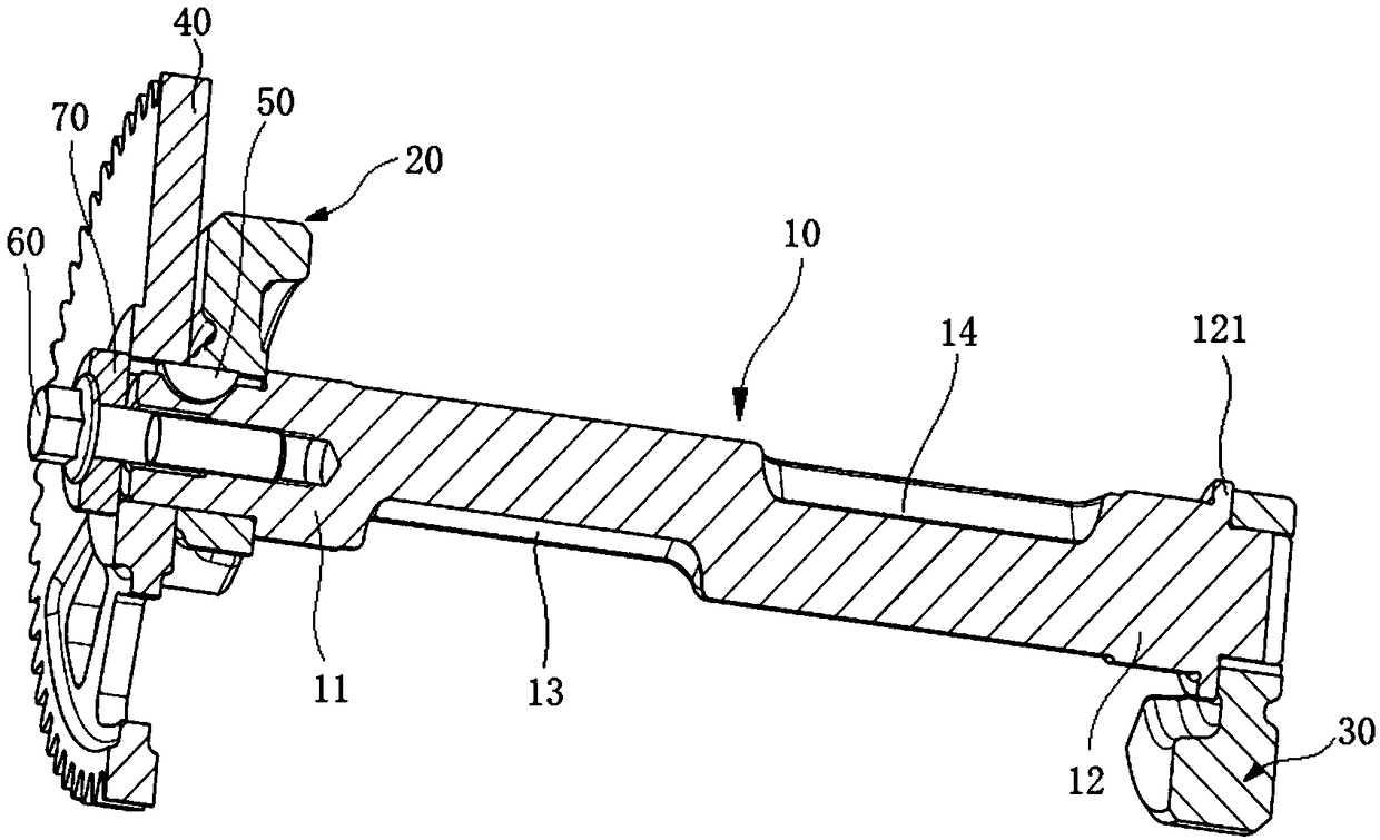
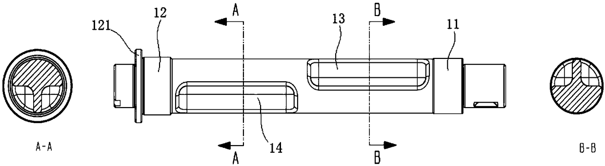
[0012] A three-cylinder engine balance shaft, comprising a balance shaft 10, a front balance weight 20 installed at the front end of the balance shaft 10, a rear balance weight 30 installed at the rear end of the balance shaft, and a balance shaft drive gear 40, the rear balance weight 30 Set on the rear end of the rear journal 12 of the balance shaft 10, the front balance weight 20 and the balance shaft drive gear 40 are sequentially connected to the front end of the front journal 11 of the balance shaft 10 by the key 50, and the mass of the rear balance weight 30 is greater than that of the front balance shaft. The mass of the weight 20, the eccentric arrangement directions of the front balance weight 20 and the rear balance weight 30 are opposite. The balance shaft 10, the front balance weight 20, the rear balance weight 30 and the balance shaft drive gear 40 form a balance system, which ...


PUM


Abstract

The invention discloses a balance shaft of a three-cylinder engine. The balance shaft comprises a balance shaft body, a front balance block installed at the front end of the balance shaft body, a rearbalance block installed at the rear end of the balance shaft body, and a balance shaft drive gear; and the rear balance block thermally sleeves the rear end of a rear shaft neck of the balance shaftbody, the front balance block and the balance shaft drive gear are sequentially connected to the front end of a front shaft neck of the balance shaft body through keys, the mass of the rear balance block is larger than that of the front balance block, and the eccentric arrangement direction of the front balance block and the eccentric arrangement direction of the rear balance block are opposite. The balance shaft body, the front balance block, the rear balance block and the drive gear form a balance system, when the balance system rotates along with the engine, the rotating direction of the balance system is opposite to the rotating direction of a crankshaft of the engine, and the rotating speed of the balance system is the same as the rotating speed of the crankshaft, so that first-orderreciprocating inertia moment generated by a piston connecting rod assembly is counteracted, then the vibration of the engine is reduced, and the comfort of an automobile is improved.

Description

technical field [0001] The invention relates to the technical field of balance of a three-cylinder engine crank connecting rod mechanism, specifically a three-cylinder engine balance shaft. Background technique [0002] Under the circumstances of increasingly tight petroleum energy supply and stricter emission requirements, major automobile manufacturers have turned to the development of energy-saving and environment-friendly engines. The engine has a small displacement and light weight, and its fuel consumption on the vehicle is relatively low. With the application of technologies such as supercharged direct injection, more and more three-cylinder engines are applied to automobiles. Compared with the widely used four-cylinder engines, the fuel consumption of three-cylinder engines is significantly reduced. favored by the factory. [0003] Since the working principle of the engine itself is that each cylinder is ignited in sequence at different times to perform external wo...

Claims


Application Information

Patent Timeline
Patent Type & Authority Applications(China)
IPC IPC(8): F16F15/26
CPCF16F15/262
Inventor 王知王超王浩王先义
Owner CHERY AUTOMOBILE CO LTD
Why Eureka
Try Eureka