

High-efficiency heat exchanger flow passage structure, air conditioner and heat exchange method
A technology of heat exchangers and thermal methods, applied in the direction of indirect heat exchangers, heat exchanger types, heating methods, etc., can solve the problems of low heat exchange capacity and poor heat exchange effect of heat exchangers, and achieve heat exchange efficiency High, good heat exchange effect, good user experience
- Summary
- Abstract
- Description
- Claims
- Application Information
AI Technical Summary
Problems solved by technology
Method used
Image

Examples
Embodiment
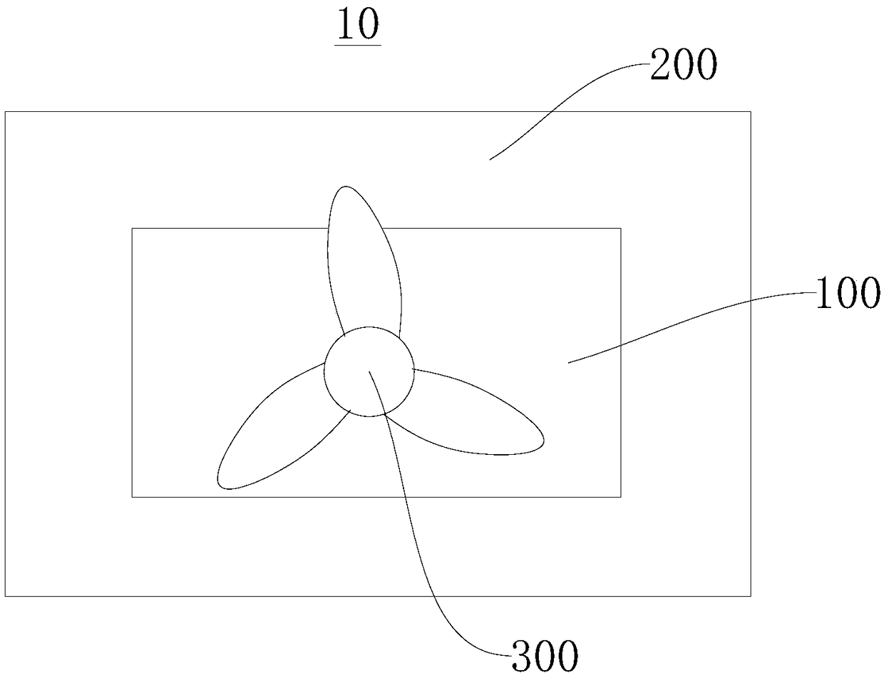
[0041] Please refer to figure 1 , the embodiment of the present invention provides an air conditioner 10 for cooling or heating indoors. Its structure is simple, and it can realize the forward flow and reverse flow of the refrigerant relative to the air flow direction, improve the heat exchange rate, high heat exchange efficiency, good heat exchange effect, and better user experience. The air conditioner 10 includes a heat exchanger 100 , a casing 200 and a fan 300 . The fan 300 and the heat exchanger 100 are installed in the casing 200 to exchange heat with the external airflow. The fan 300 sucks in air from the outside and blows out an airflow to the heat exchanger 100. The heat exchanger 100 exchanges heat for the airflow, and the heat-exchanged air is delivered to the room through the shell 200 to achieve cooling or heating effects.
[0042] It should be noted that, in this embodiment, the heat exchanger 100 is an outdoor unit condenser, but it is not limited thereto, an...
PUM
 Abstract
Description
Claims
Application Information