A Method for Accurately Measuring the Lateral Resolution of a Focused Ultrasound Transducer

A technology of lateral resolution and focused ultrasound, applied in measuring devices, material analysis using sound waves/ultrasonic waves/infrasonic waves, instruments, etc., can solve problems such as the impact of imaging clarity and the complexity of the measurement process

Active Publication Date: 2020-10-30
UNIV OF SCI & TECH BEIJING
View PDF4 Cites 0 Cited by
  • Summary
  • Abstract
  • Description
  • Claims
  • Application Information

AI Technical Summary

Problems solved by technology

If the radial sound pressure distribution of the focal plane of the focused ultrasonic transducer is measured experimentally, the measurement results will inevitably be affected by the receiving device, and the calculation of the radial sound pressure distribution of the focal plane of the focused ultrasonic transducer according to the theoretical formula must be considered The spectral characteristics of the actual transducer, so the whole measurement process is more complicated
If the lateral resolution of the focused ultrasound transducer is judged based on the clarity of the standard grating pattern in the C-scan image, a series of grating stripes with different spacings need to be prepared on the test block. This method not only has a high impact on the processing accuracy of the test block requirements, and the imaging clarity will inevitably be affected by the axial resolution

Method used


Image

  • A Method for Accurately Measuring the Lateral Resolution of a Focused Ultrasound Transducer
  • A Method for Accurately Measuring the Lateral Resolution of a Focused Ultrasound Transducer
  • A Method for Accurately Measuring the Lateral Resolution of a Focused Ultrasound Transducer

Examples


Embodiment Construction

[0025] In order to make the technical problems, technical solutions and advantages to be solved by the present invention clearer, the following will describe in detail with reference to the drawings and specific embodiments.

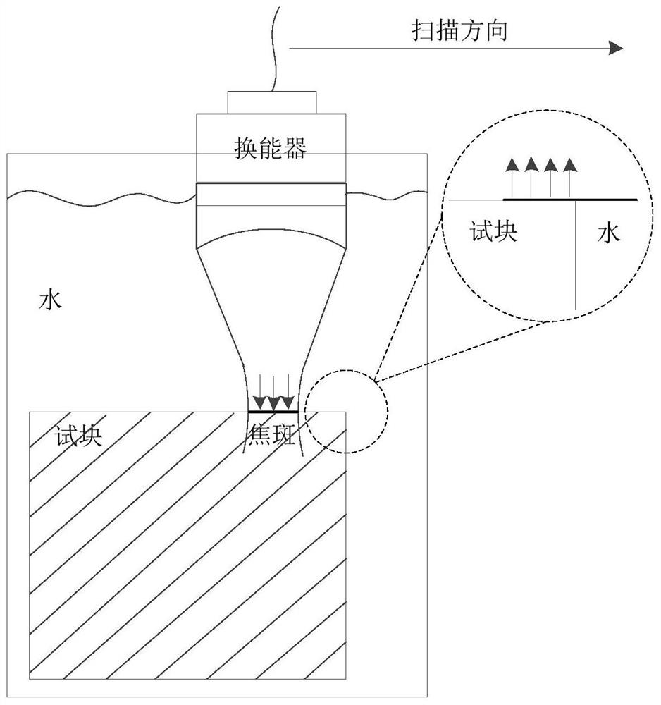
[0026] The invention provides a method for accurately measuring the lateral resolution of a focused ultrasonic transducer.

[0027] The method steps are as follows:

[0028] (1) Processing the stainless steel material into a cube test block;

[0029] (2) Carry out high-precision C-scan imaging to the edge of the cube test block prepared in step (1) with the focused ultrasonic transducer to be tested;

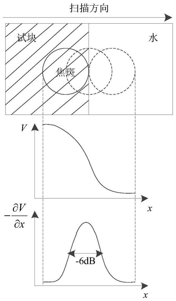
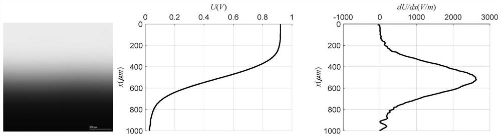
[0030] (3) Randomly select 10 gray value curves V(x) perpendicular to the edge of the test block in the C-scan image in step (2), average them and then use the mean value filter method to smooth the gray value curves;

[0031] (4) Derivation operation is performed on the smoothed gray value curve in step (3) to obtain the gray value change rate curve ...


PUM


Abstract

The invention provides a method for accurately measuring transverse resolution of a focusing ultrasonic transducer, which belongs to the technical field of ultrasonic detection. The method is characterized in that a stainless steel material is processed to a cube test block, and the edge of the test block is sharp without chamfer; a to-be-measured focusing ultrasonic transducer is used for performing high-precision C scan imaging on the edge of the test block; 10 gray value curves V(x) which is perpendicular to the edge of the test block in a C scan image are selected at random, and the 10 gray value curves are averaged, an average filtering method is used for smoothing processing on the gray value curves, the gray value curve after smoothing is subjected to a derivation operation to obtain a gray value rate change curve, and finally a -6dB descent method is employed for calculating the transverse resolution of the focusing ultrasonic transducer according to the gray value rate changecurve. The method for accurately measuring the transverse resolution of the focusing ultrasonic transducer on experiment is simple, and the influence of the transverse resolution on the C scan imagingresolution is visually displayed. The method has low preparation requirement on the test block, and the same test block is suitable for different types of the axisymmetric energy transducers.

Description

technical field [0001] The invention relates to the technical field of ultrasonic detection, in particular to a method for accurately measuring the lateral resolution of a focused ultrasonic transducer. Background technique [0002] The lateral resolution of the focused ultrasonic transducer is one of the important parameters affecting the detection accuracy and imaging quality of the ultrasonic microscope, and determines the clarity of the C-scan imaging. The lateral resolution of the focused ultrasonic transducer is related to the numerical aperture of the transducer and the wavelength of the acoustic wave. By improving the degree of convergence of the acoustic waves emitted by the transducer in the material to be tested, the lateral resolution of the focused ultrasonic transducer can be effectively improved. At present, the methods for determining the lateral resolution of the focused ultrasonic transducer are roughly divided into the following three types: 1) According t...

Claims


Application Information

Patent Timeline
Patent Type & Authority Patents(China)
IPC IPC(8): G01N29/30
CPCG01N29/30
Inventor 肖会芳陈丹安元卜
Owner UNIV OF SCI & TECH BEIJING
Why Eureka
Try Eureka