Supercharge Your Innovation With Domain-Expert AI Agents!

A method of controlling the coaxiality of cathode and anode of magnetron with positioning ceramic ring

A technology of magnetron and coaxiality, applied in magnetrons, discharge tubes, time-of-flight electron tubes, etc., can solve the problem of lower working voltage of the whole tube, poor batch production consistency, and difficulty in accurately ensuring the coaxiality of cathode and anode Degree and other issues

Active Publication Date: 2019-07-05
XI AN JIAOTONG UNIV +1
View PDF4 Cites 0 Cited by
  • Summary
  • Abstract
  • Description
  • Claims
  • Application Information

AI Technical Summary

Problems solved by technology

There is a voltage difference of several thousand to tens of thousands of volts between the cathode and anode of the magnetron, and a certain distance must be kept between the cathode and anode to achieve electrical isolation, which cannot be achieved by the traditional method of relying on the structural size of the parts themselves
The traditional magnetron uses the cathode and anode coaxial mold to position the cathode during the assembly process. After the cathode is welded and fixed, it is demolded. Due to the thermal stress of the cathode during the welding process, the cathode will be eccentric in a certain direction after demolding. It is difficult to accurately guarantee the coaxiality of the cathode and anode, especially when the cathode is heated, the eccentricity becomes more prominent as the temperature rises, which leads to a drop in the working voltage of the whole tube and a decrease in working efficiency, which directly affects the working performance of the whole tube and leads to consistent batch production Poor performance, lower yield rate, not conducive to high-efficiency production

Method used


Image

  • A method of controlling the coaxiality of cathode and anode of magnetron with positioning ceramic ring
  • A method of controlling the coaxiality of cathode and anode of magnetron with positioning ceramic ring
  • A method of controlling the coaxiality of cathode and anode of magnetron with positioning ceramic ring

Examples


Embodiment Construction

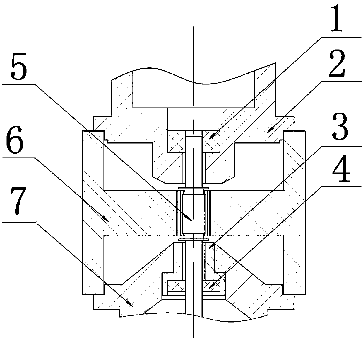
[0018] A method for controlling the coaxiality of the anode and cathode of a magnetron by using a positioning ceramic ring, using a ceramic ring with the coaxial positioning of the cathode and anode, the ceramic ring and the cathode are fixed in the tube core, and the cathode and anode can always be guaranteed no matter in any state The coaxiality meets the requirements, which is achieved through the following steps:

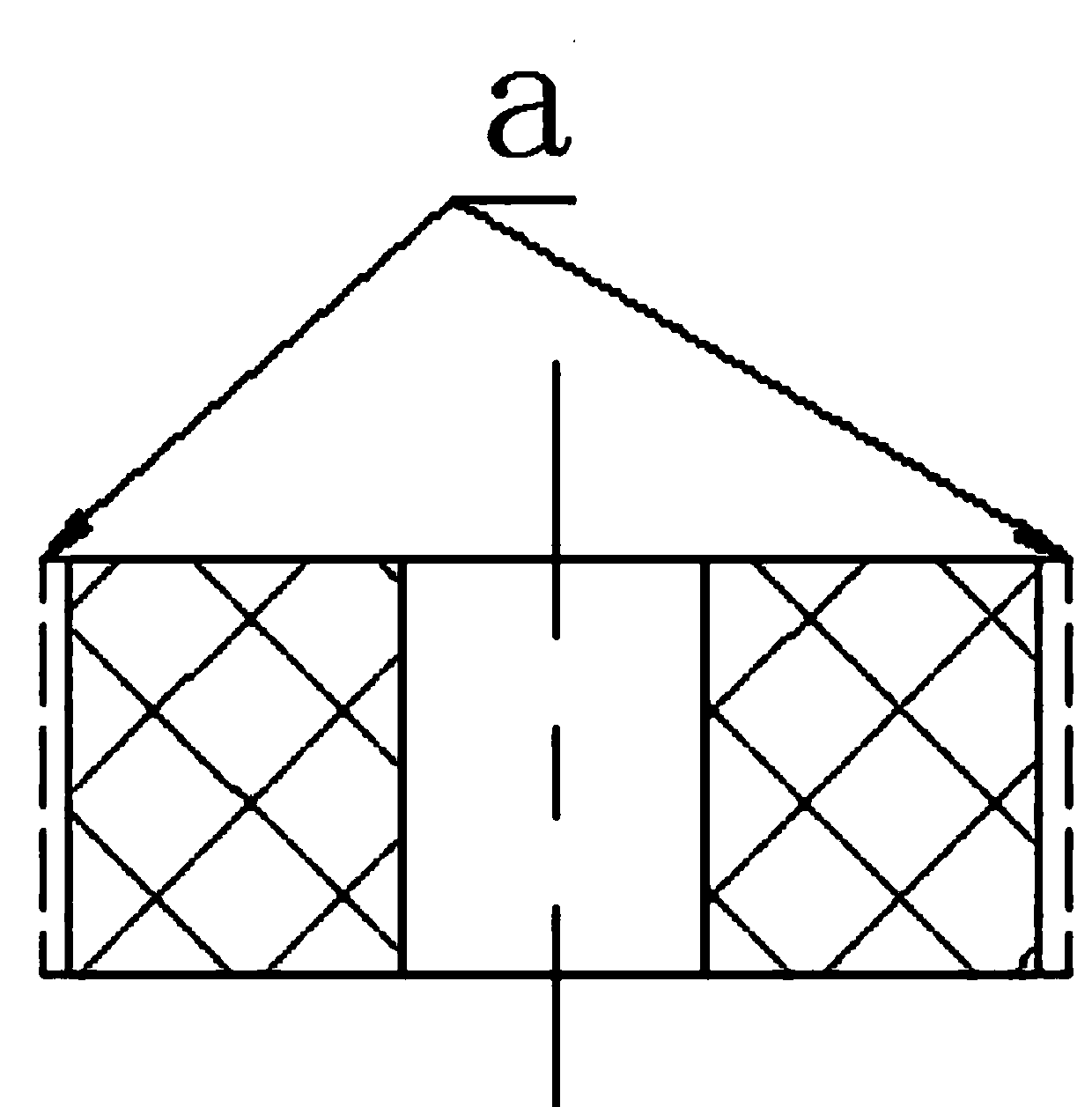
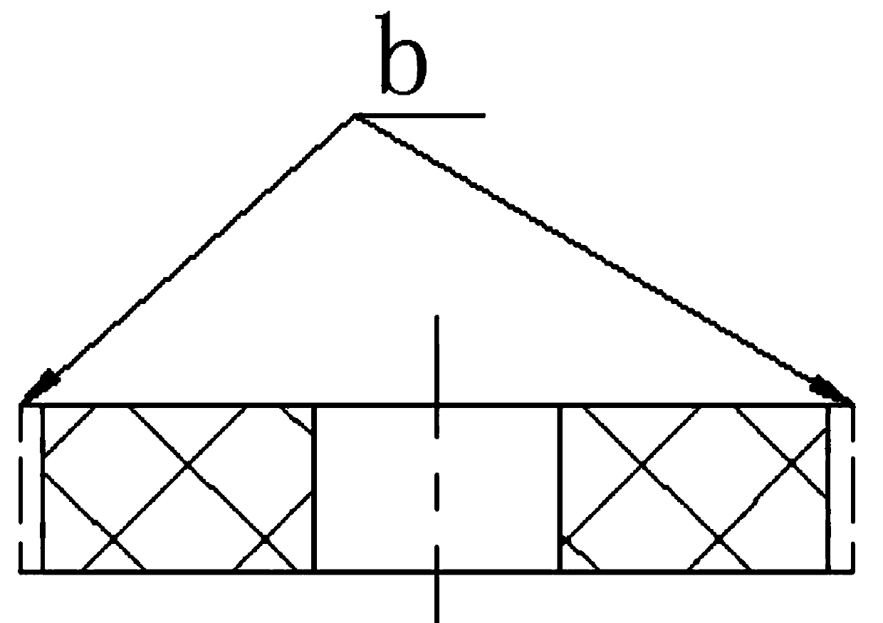
[0019] Step (1). Use Al 2 o 3 The ceramic ring is formed by powder pressing and sintered at high temperature, and then the upper coaxial positioning ceramic ring 1 (such as figure 1 shown) and the lower coaxial positioning ceramic ring 4 (such as figure 2 As shown), the coaxiality of the positioning ceramic ring is a necessary condition to ensure the coaxiality of the cathode and anode of the magnetron. Therefore, it is necessary to ensure that the coaxiality of the positioning ceramic ring meets the requirements during processing;

[0020] Step (2). After m...


PUM

PropertyMeasurementUnit
thicknessaaaaaaaaaa

Abstract

The invention belongs to basic electrical elements in electricity, and provides a method for controlling coaxiality of an anode and a cathode of a magnetron by using a positioning ceramic ring; a ceramic ring is prepared by press molding through Al2O3 and then high-temperature sintering, an upper coaxial positioning ceramic ring and a lower coaxial positioning ceramic ring which are coaxial are respectively formed through grinding and are correspondingly installed on pole shoe holes of an upper pole shoe and a lower pole shoe head respectively, and a cathode rod, the upper pole shoe hole and the lower pole shoe hole are coaxially fixed through the coaxial positioning ceramic rings, so that the electric isolation between the cathode and the anode can be guaranteed, and on the other hand, the coaxiality of the cathode and the anode is positioned by the ceramic rings in the upper pole shoe and the lower pole shoe, the cathode and the anode are fixedly welded in a tube core together, and the coaxiality of the cathode and the anode can be always guaranteed to meet the requirements in any state.

Description

technical field [0001] The invention belongs to basic electrical components in electricity, relates to a magnetron, in particular to a method for controlling the coaxiality of the cathode and anode of the magnetron by using a positioning ceramic ring. Background technique [0002] The coaxiality of the cathode and anode of the magnetron has a great influence on the performance of the magnetron, and plays a decisive role in the efficiency and working voltage of the magnetron. There is a voltage difference of several thousand to tens of thousands of volts between the cathode and anode of the magnetron. A certain distance must be kept between the cathode and anode to achieve electrical isolation, which cannot be achieved by the traditional method of positioning by the structural size of the part itself. In the traditional magnetron, the cathode and anode coaxial molds are used to position the cathode during the assembly process. After the cathode is welded and fixed, the mold i...

Claims


Application Information

Patent Timeline
Patent Type & Authority Patents(China)
IPC IPC(8): H01J23/02H01J25/50
CPCH01J23/02H01J25/50
Inventor 马正军牛文斗穆建中
Owner XI AN JIAOTONG UNIV
Features
  • R&D
  • Intellectual Property
  • Life Sciences
  • Materials
  • Tech Scout
  • Unparalleled Data Quality
  • Higher Quality Content
  • 60% Fewer Hallucinations
Learn More