
Local unowned bus protection realization method

A busbar protection and implementation method technology, applied in the direction of emergency protection circuit devices, electrical components, etc., can solve the problems of large size, reduced speed and reliability, and large number of devices, and achieve the effect of small size and reduced busbar protection devices

Pending Publication Date: 2018-08-14
NR ELECTRIC CO LTD +1
View PDF5 Cites 8 Cited by
  • Summary
  • Abstract
  • Description
  • Claims
  • Application Information

AI Technical Summary

Problems solved by technology

The protection device of the conventional substation is installed in the protection control room, far away from the primary equipment switch, resulting in the need to use a large number of cables for connection, which requires a large investment
The smart substation adopts the "three-layer two-network" system architecture, the merging unit, intelligent terminal and other equipment are installed near the primary equipment, and the protection device is installed in the protection control room, resulting in a large number of optical cables and some new problems. For example, the number of protection sampling and tripping links increases, and the speed and reliability decrease; the network structure is complex and the number of switches is large
[0003] In addition, the traditional centralized busbar protection has a large volume due to the collection of analog and switch data on each side. If it is installed locally, the cable distance will be longer and the number of devices will be larger.

Method used


Image

  • Local unowned bus protection realization method
  • Local unowned bus protection realization method

Examples


Embodiment Construction

[0013] The protection method of the non-hosted in-situ bus protection device of the present invention will be described in detail below in conjunction with the accompanying drawings.

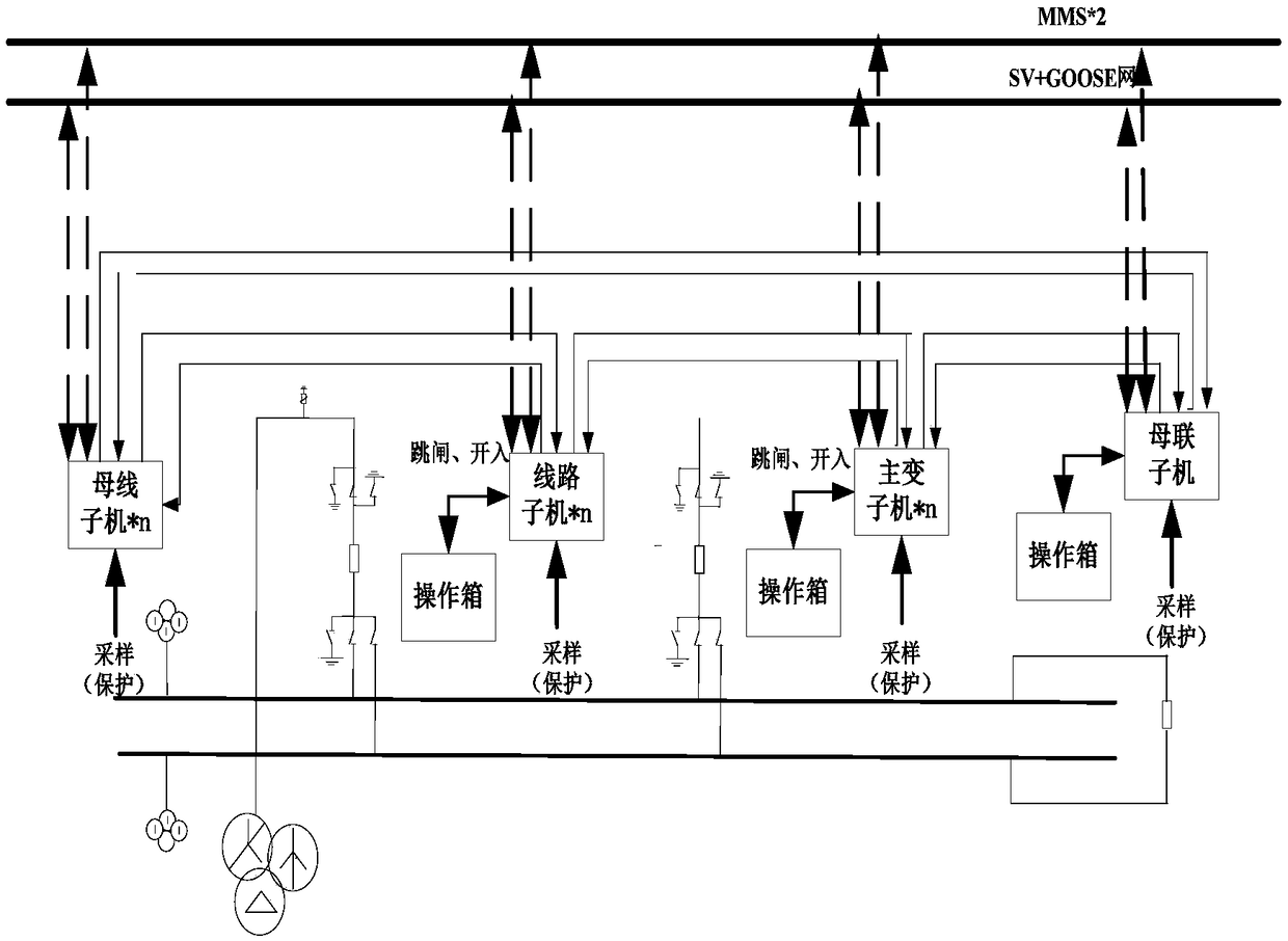
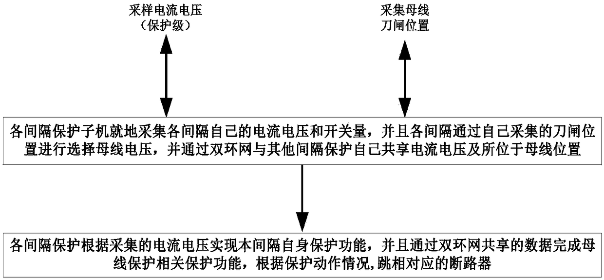
[0014] Such as figure 1 with figure 2 As shown in the figure, an on-site unmaintained bus protection device includes multiple line protection sub-units, multiple main transformer protection sub-units, bus tie protection sub-units, sub-section protection sub-units, bus voltage sub-units, and each protection sub-unit The machines are connected through the hand-in-hand double-ring network, and each protection sub-machine collects its own current, voltage analog and busbar switch switch on the spot, so as to realize the self-protection of each protection interval (that is, the line protection sub-machine realizes the line protection function, The main transformer protection sub-unit realizes the main transformer protection function, the bus-tie protection sub-unit realizes the bus-tie protection f...


PUM


Abstract

The invention discloses a local unowned bus protection realization method. The method comprises the following steps: each internal protection son-machine adopts local protection device to realize thedistributed busbar differential protection based on a bi-directional ring network; each internal protection sub-machine locally collects the current, the voltage analog quantity and switch quantity atthis side, and bi-directionally communicates with other protection son-machines through the double-loop network to share the data; each interval protection son-machine realize the internal own protection function, for instance, the line protection son-machine realizes the line protection light equation, distance, overcurrent and like protection functions; the interval protection son-machine tripsoff the corresponding circuit breaker according to the own protection action condition and the bus difference protection action condition. Each interval local protection is used as the bus protectionson-machine, each interval local protection only collects the analog quantity and the switch quality of this side, and the data is shared through the double-loop network, so that the son-machine is small in volume and can be locally installed, and the original bus protection device is reduced.

Description

technical field [0001] The invention relates to the technical field of electric power system relay protection, in particular to a method for realizing on-site non-owner bus protection. Background technique [0002] At present, the substations are divided into conventional substations and smart substations. The protection devices of conventional substations are installed in the protection control room, away from the primary equipment switch, resulting in the need to use a large number of cables for connection, which requires a large investment. The smart substation adopts the "three-layer two-network" system architecture, the merging unit, intelligent terminal and other equipment are installed near the primary equipment, and the protection device is installed in the protection control room, resulting in a large number of optical cables and some new problems. For example, the number of protection sampling and tripping links increases, and the speed and reliability decrease; t...

Claims


Application Information

Patent Timeline
IPC IPC(8): H02H7/22
CPCH02H7/22
Inventor 宋湘萍牟长玖王凯何学东顾健雨赵雷潘仁秋姬生飞李兴华鲁新意施挺肖杨
Owner NR ELECTRIC CO LTD
Learn More