Dust removing device for rotary die cutting machine

The technology of a dust removal device and a die-cutting machine is applied in the direction of cleaning methods and utensils, chemical instruments and methods, etc., which can solve the problems of die-cut product pollution, high cost, dirty products and foreign matter defects, and achieve the reduction of refueling time, Stable operation and good dust removal effect

Inactive Publication Date: 2018-08-17
SHENZHEN CDL PRECISION TECH CO LTD
View PDF7 Cites 5 Cited by
  • Summary
  • Abstract
  • Description
  • Claims
  • Application Information

AI Technical Summary

Problems solved by technology

Die-cut products are usually used on precision parts, and during the material cutting process, dust and debris may be generated at the edge of the material. When using a rotary die-cutting machine for production, the dust and debris will be adsorbed on the rubber shaft. The product causes pollution, which makes the product dirty and foreign matter bad. Therefore, it is necessary to remove dust or maintain a dust-free environment during production. For example, some directly use dust-free production workshops, but the cost is very high; more often use special dust removal devices For example, patent CN201620252764.4 discloses a mesh dedusting device, which includes a winding mechanism, a cutting mechanism and a sticky stick group. The winding mechanism winds the raw material, and the cutting mechanism passes through the raw material. The sticky stick group is in contact with the surface of the raw material. The sticky stick set is composed of a plurality of adjacent and interlocking rubber rollers. Scraper for crumbs, when the sticky dust stick group is used for dust removal, the scraper will scrape off the crumbs and dust on the rubber roller and suck the dust and crumbs on the cutter head through the vacuum cleaner; another example is the patent CN201620816179.2 It is a dust removal structure of a circular knife die-cutting machine, including a fixing mechanism, an adjustment bracket, and a dust removal mechanism; one end of the fixing mechanism is fixed on the body of the round knife die-cutting machine, and the other end is connected with the dust removal mechanism through an adjustment bracket. An adjustment unit that can adjust the angular position of the dust removal mechanism is added to the adjustment bracket; the dust removal mechanism is rotatably connected with the adjustment bracket, and the dust removal mechanism includes a dust removal roller and a dust removal film roll that is originally wound on the dust removal roller; The above-mentioned dust removal rollers are fixedly connected to the adjustment bracket through bolts; these dust removal devices can only be applied to specific corresponding die-cutting machines, and the scope of use is relatively narrow, and there are phenomena such as incomplete dust removal or easy damage to die-cutting machine components.

Method used


Image

  • Dust removing device for rotary die cutting machine

Examples


Embodiment 1

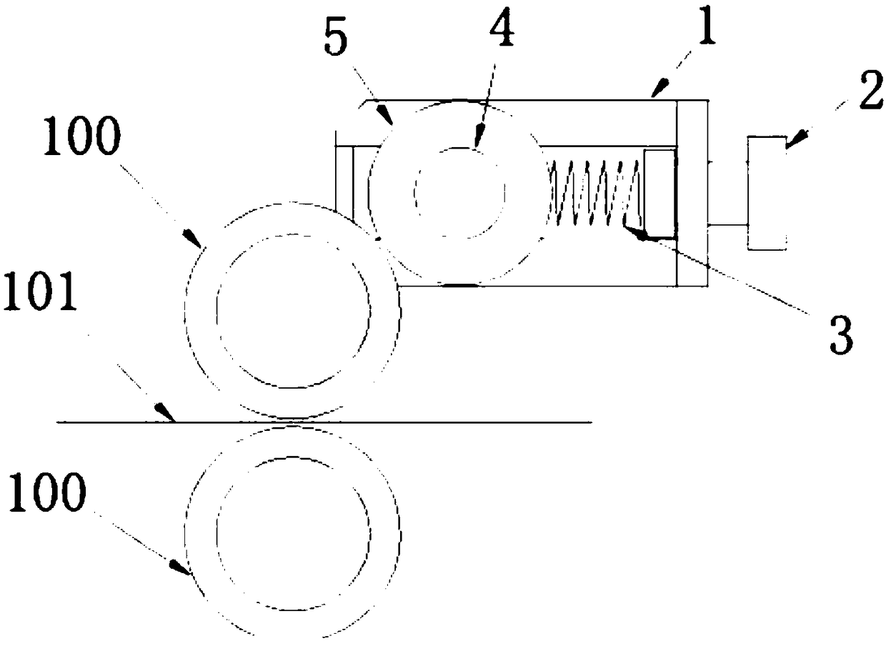
[0021] The dust removal device of the rotary die cutting machine includes a base 1, an adjusting bolt 2, a telescopic assembly 3, an axis 4 and a sticky roller 5, the diameter of the axis 4 is 20mm, and the outer diameter of the sticky roller 5 is 40mm , the diameter of the rubber shaft 100 is 100mm, the bonding force between the sticky roller 5 and the rubber shaft 100 is 40N, and the dust removal device of the rotary die cutting machine operates stably.

Embodiment 2

[0023] The dust removal device of the rotary die-cutting machine includes a base 1, an adjusting bolt 2, a telescopic assembly 3, an axis 4 and a sticky roller 5, the diameter of the axis 4 is 30mm, and the outer diameter of the sticky roller 5 is 50mm , the diameter of the rubber shaft 100 is 80mm, the bonding force between the dust-sticking roller 5 and the rubber shaft 100 is 30N, the material of the dust-sticking roller 5 is PET and the surface is coated with acrylic glue, the rotary mold The cutting dust removal device operates stably.

Embodiment 3

[0025] The dust removal device of the rotary die cutting machine includes a base 1, an adjusting bolt 2, a telescopic assembly 3, an axis 4 and a sticky roller 5, the diameter of the axis 4 is 40mm, and the outer diameter of the sticky roller 5 is 60mm , the diameter of the rubber shaft 100 is 90mm, the bonding force between the sticky roller 5 and the rubber shaft 100 is 40N, and the dust removal device of the rotary die cutting machine operates stably.

[0026] By producing the dust removal device of the rotary die cutting machine obtained in Examples 1 to 3, the dust and debris adsorbed on the rubber shaft can be better sticked away, the dust removal effect is better and the operation is stable, and it can also reduce The refueling time meets the requirements of reducing product pollution and reducing defects.


PUM


Abstract

The invention relates to the technical field of die cutting machines, particularly relates to rotary die cutting machines and specifically provides a dust removing device for a rotary die cutting machine. The dust removing device for the rotary die cutting machine comprises a pedestal, a regulating bolt, a telescopic component, an axis and a dust sticking roller; the pedestal is fixedly installedat one side of a rubber shaft; a telescopic component is installed inside the pedestal; the regulating bolt is in threaded connection with one side surface of the pedestal; the tail end of the regulating bolt extends into the pedestal and is connected with one end of the telescopic component; the other end of the telescopic component is connected with the axis; the axis can slide inside the pedestal under the driving of the telescopic component; and the dust sticking roller is rotationally arranged on the axis in a sleeving manner. The dust removing device provided by the invention can make the dust sticking roller and the rubber shaft closely cling to each other so as to take away dust and fragments which are adsorbed on the rubber shaft in a sticking way, realizes a better dust removal effect, runs stably, can also shorten the material replacement time, can prevent an incomplete adhesion effect caused by too small force, and can also prevent easy damage of the dust sticking roller due to too large force.

Description

Technical field: [0001] The invention relates to the technical field of die-cutting machines, in particular to a rotary die-cutting machine, and specifically provides a dust removal device for a rotary die-cutting machine. Background technique: [0002] The main processing procedure in the die-cutting industry is to use professional die-cutting equipment and molds to cut and process materials to obtain products of the desired shape; die-cut products are widely used in various industries, such as electronics, IT industry membrane switches and Adhesive products used in the automobile manufacturing industry, such as dust-proof materials such as cotton pads, dust-proof nets and non-woven fabrics, as well as shock-proof products such as pull-back rubber pads and transparent foot pads, as well as insulating materials, EMI shielding materials, resistant Thermal insulation materials and paper packaging materials, etc. Die-cut products are usually used on precision parts, and during...

Claims


Application Information

Patent Timeline
Patent Type & Authority Applications(China)
IPC IPC(8): B08B7/00
CPCB08B7/0028
Inventor 周石岐张国书汪继洋余晓峰吴飞煌
Owner SHENZHEN CDL PRECISION TECH CO LTD
Why Eureka
Try Eureka