Exhaust pipe machining device

A processing device and exhaust pipe technology, which is applied in the field of auto parts processing, can solve problems such as the distortion of the cross-sectional shape of the exhaust pipe, and achieve the effect of easy deformation

Active Publication Date: 2018-08-17
宁波高新区新柯保汽车科技有限公司
View PDF10 Cites 1 Cited by
  • Summary
  • Abstract
  • Description
  • Claims
  • Application Information

AI Technical Summary

Problems solved by technology

[0005] The purpose of the present invention is to provide an exhaust pipe processing device to solve the problem that the cross-sectional shape is easily deformed when the exhaust pipe is bent

Method used


Image

  • Exhaust pipe machining device
  • Exhaust pipe machining device
  • Exhaust pipe machining device

Examples


Embodiment Construction

[0026] The following is further described in detail through specific implementation methods:

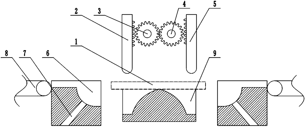
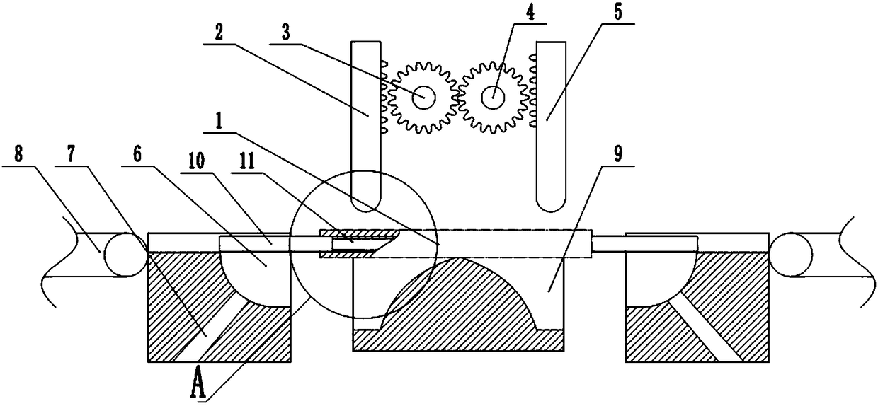
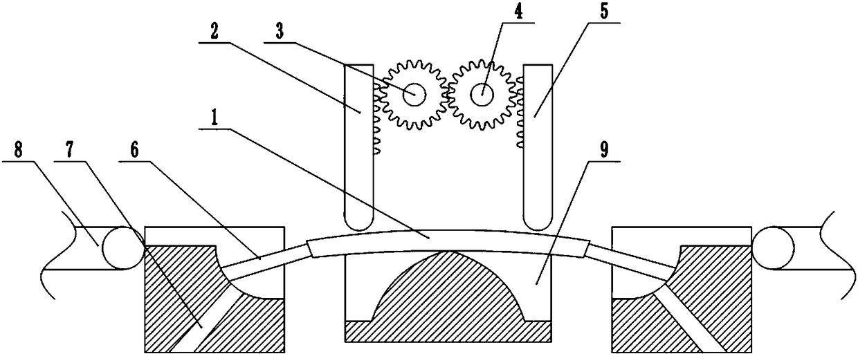
[0027] The reference signs in the accompanying drawings include: exhaust pipe 1, first rack 2, first gear 3, second gear 4, second rack 5, chute 6, through hole 7, conveyor belt 8, placement slot 9. Rigid segment 10, flexible segment 11, bump 12, reed 13.

[0028] like figure 1 As shown, the exhaust pipe 1 processing device includes a frame, and a workbench is fixed on the frame. The upper surface of the workbench is provided with a placement groove 9, and the bottom of the placement groove 9 is arc-shaped with two ends bent downward, and the exhaust pipe 1 is placed in the placement groove 9, when the exhaust pipe 1 is bent, the bottom of the placement groove 9 will not hinder the downward movement of both ends of the exhaust pipe 1. An electric heater is provided at the center of the bottom of the placement groove 9. When the exhaust pipe 1 is bent, the electric heater can be use...


PUM


Abstract

The invention belongs to the field of automobile part machining, and particularly discloses an exhaust pipe machining device. The device comprises a machine frame, wherein a workbench is arranged on the machine frame, a placing groove is formed in the upper surface of the workbench, and the bottom of the containing groove is arc-shaped; bent parts are symmetrically arranged on the two sides of thecontaining groove in the machine frame, the bending parts comprise sliding grooves arranged on the machine frame, the sliding grooves comprise horizontal sections and arc sections, and through holesare formed in the arc section; bending rods are slidably connected in the sliding grooves, the bending rods comprise flexible sections and rigid sections, storage cavities are formed in the flexible sections, and hydrochloric acid and sodium carbonate are correspondingly arranged in the storage cavities of the two flexible sections; discharging openings are formed in the flexible section; the lower pressing unit comprises a first gear and a second gear, the first gear is rotationally connected to the machine frame, and the second gear is meshed with the first gear; and the lower pressing unitfurther comprises a first rack and a second rack which are connected to the machine frame in a sliding mode, and stamping heads are arranged at the lower ends of the first rack and the second rack. Bythe adoption of the scheme of the exhaust pipe machining device, the problem that cross section shape distortion is easily caused when the exhaust pipe is bent is solved.

Description

technical field [0001] The invention belongs to the field of auto parts processing, and in particular relates to an exhaust pipe processing device. Background technique [0002] The exhaust pipe is installed between the engine exhaust manifold and the muffler, so that the entire exhaust system is flexibly connected, thereby reducing vibration and noise, facilitating installation and prolonging the life of the exhaust muffler system. The exhaust pipe is mainly Applied to light vehicles, mini-cars and passenger cars. [0003] During the processing of the exhaust pipe, the exhaust pipe is often bent with a pipe bender after the exhaust pipe is processed into a straight pipe. The pipe bender consists of a table for placing the exhaust pipe and punches on both sides of the table. When in use, first place the pipe on the workbench, align the two ends of the exhaust pipe with the stamping head, start the pipe bender, slide the stamping head down and press the two ends of the exha...

Claims


Application Information

Patent Timeline
IPC IPC(8): B21D9/01B21D9/16B21D9/18
CPCB21D9/01B21D9/16B21D9/18
Inventor 王作栋
Owner 宁波高新区新柯保汽车科技有限公司
Why Eureka
Try Eureka