Automatic feed mechanism of numerical control lathe

A technology of automatic feeding and CNC lathes, which is applied in the direction of automatic in/out of workpieces, metal processing machine parts, metal processing, etc., which can solve the problem of increasing the time for opening and closing the door, the time for the arm to extend out of the machine tool, the different proficiency of the workers, and the difficulty of the operator Master and other issues to achieve the effect of fast and unified production cycle, improve operation efficiency, and improve work safety performance

Pending Publication Date: 2018-08-17
福鼎市三宏机车部件有限公司
View PDF0 Cites 3 Cited by
  • Summary
  • Abstract
  • Description
  • Claims
  • Application Information

AI Technical Summary

Problems solved by technology

Manual clamping requires frequent operation of the machine, long-term operation is prone to fatigue and misuse, manual clamping requires frequent machine operation, long-term operation is prone to fatigue and misoperation, and a worker in manual clamping can only operate 2 CNC lathes at most , manual clamping due to the different proficiency of workers, resulting in difficult control of the production cycle
Problems with automation devices such as truss-type and articulated manipulators: These two devices are external structures of the machine tool. When changing materials, the machine tool must first open the door before the mechanical arm can reach into the machine tool for grabbing. After the grabbing is completed, the arm moves out of the machine tool and then Close the door of the machine tool, so the time for opening and closing the door and the time for extending the arm into and out of the machine tool are increased; the structure of these two devices is complicated and the cost is high; It is necessary to replace the corresponding claws and trays; when installing the truss manipulator, it is necessary to consider the top space of the machine tool (the interference area when the arm moves), and the articulated manipulator needs to consider the space at the front end or around the machine tool (the interference area when the arm moves); The actions of the above two devices are relatively complicated and difficult for operators to master

Method used


Image

  • Automatic feed mechanism of numerical control lathe
  • Automatic feed mechanism of numerical control lathe
  • Automatic feed mechanism of numerical control lathe

Examples


Embodiment Construction

[0027] In order to explain in detail the technical content, structural features, achieved goals and effects of the technical solution, the following will be described in detail in conjunction with specific embodiments and accompanying drawings.

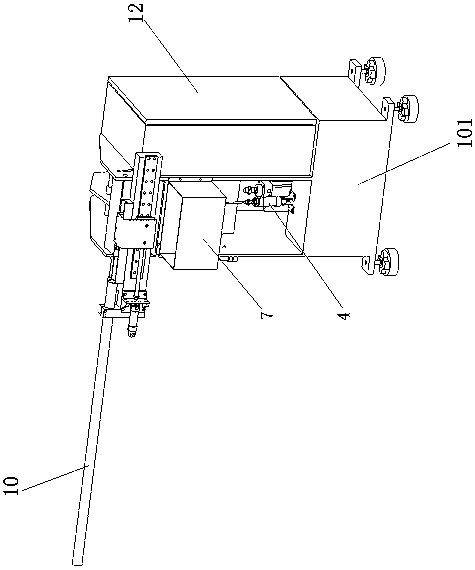
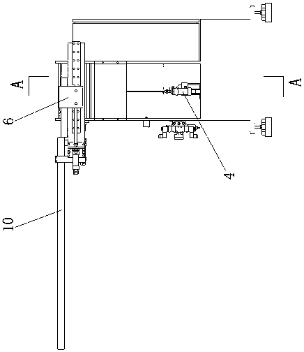
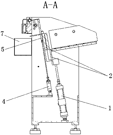
[0028] see Figure 1-Figure 5 As shown, a kind of CNC lathe automatic feeding mechanism of the present embodiment includes a workbench 101, the bottom of the workbench 101 is provided with a jacking cylinder 1, and the upper part of the workbench 101 is provided with a jacking plate 2, and the jacking cylinder 1 is used to push the lifting plate 2 to move, and the workbench 101 is provided with a detection position, and the lifter plate 2 is used to push the workpiece into the detection position on the workbench 101, and the workbench 101 is also provided with a positive Reverse identification device 3, the positive and negative identification device 3 is arranged at the detection position, the positive and negative identification dev...


PUM


Abstract

The invention relates to the technical field of machines, in particular to an automatic feed mechanism of a numerical control lathe. The automatic feed mechanism comprises a workbench. A jacking air cylinder is arranged at the bottom of the workbench. A jacking plate is arranged on the middle upper portion of the workbench. The jacking air cylinder is used for pushing the jacking plate to move. Adetection station is arranged on the workbench. The jacking plate is used for pushing a workpiece to enter the detection station on the workbench. A forward and backward recognition device is furtherarranged on the workbench and is arranged at the detection station and used for recognizing the direction of the workpiece. A material return gate is arranged on one side of the workbench and is opened and closed through a material return air cylinder. A material return box is arranged at an outlet of the material return gate. A feed groove is formed in the top of the workbench. One end of the feed groove is connected with a feed pipe. A feed air cylinder and a feed push rod are arranged on one side of the feed groove. The jacking plate pushes the workpiece to enter the feed groove. The feed push rod pushes the workpiece to horizontally move along the feed groove. The automatic feed mechanism is low in misoperation probability, low in manufacturing cost, high in safety and simple in operation.

Description

technical field [0001] The invention relates to the technical field of machinery, in particular to an automatic feeding mechanism of a numerically controlled lathe. Background technique [0002] CNC machine tools are commonly used processing equipment in the mechanical processing industry. For short-axis parts, an auxiliary feeding mechanism is usually installed on the CNC machine tool. At present, the common feeding mechanisms of CNC lathes on the market include automatic devices such as manual clamping, truss type and joint type manipulators. Manual clamping requires frequent operation of the machine, long-term operation is prone to fatigue and misuse, manual clamping requires frequent machine operation, long-term operation is prone to fatigue and misoperation, and a worker in manual clamping can only operate 2 CNC lathes at most , Due to the different proficiency of workers in manual clamping, the production rhythm is not easy to control. Problems with automation device...

Claims


Application Information

Patent Timeline
IPC IPC(8): B23B15/00
CPCB23Q7/00B23Q7/006B23Q2707/003
Inventor 王代平叶军许文忠施永传池长银方东东
Owner 福鼎市三宏机车部件有限公司
Why Eureka
Try Eureka