Anti-deformation automatic protection pneumatic bench vise

An automatic protection and anti-deformation technology, applied in vices, manufacturing tools, etc., can solve problems such as unfavorable processing efficiency, loose clamping of workpieces, extrusion deformation of workpieces, etc.

Active Publication Date: 2020-10-30
山东华源索具有限公司
View PDF10 Cites 0 Cited by
  • Summary
  • Abstract
  • Description
  • Claims
  • Application Information

AI Technical Summary

Problems solved by technology

When the existing fixture clamps the workpiece, it usually takes the two parallel surfaces of the workpiece as the reference plane, and then clamps it through the tightening device on the fixture; when the material of the workpiece is soft, the user must clamp it when clamping. Reasonably control the clamping force. If the clamping force is too small, it will cause the workpiece to be clamped loosely, and the workpiece will move during processing; if the clamping force is too large, it will cause the workpiece to be squeezed and deformed; and now Some fixtures do not have a device that can detect the clamping force, and the user also manually measures when clamping, so the error of clamping is large, which is not conducive to improving the clamping accuracy of the workpiece; at the same time, the workpiece should be clamped during the clamping process. The force is stable, and the user will have errors in the control of the clamping force during manual clamping, which will also cause damage to the workpiece
In addition, when processing a large number of workpieces, the user needs to repeat the process of clamping and dismounting. The process is cumbersome, and the user also needs to spend more time adjusting the clamping force, which is not conducive to improving the processing efficiency.

Method used


Image

  • Anti-deformation automatic protection pneumatic bench vise
  • Anti-deformation automatic protection pneumatic bench vise
  • Anti-deformation automatic protection pneumatic bench vise

Examples


Embodiment Construction

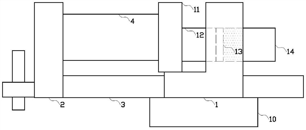
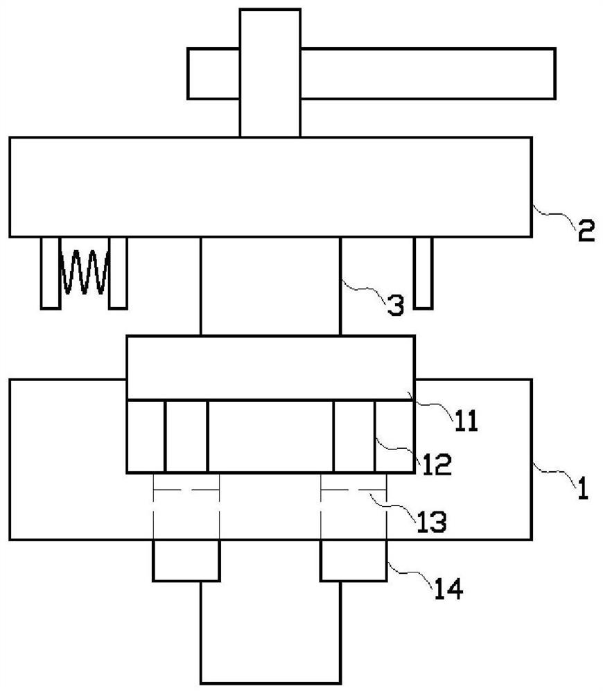
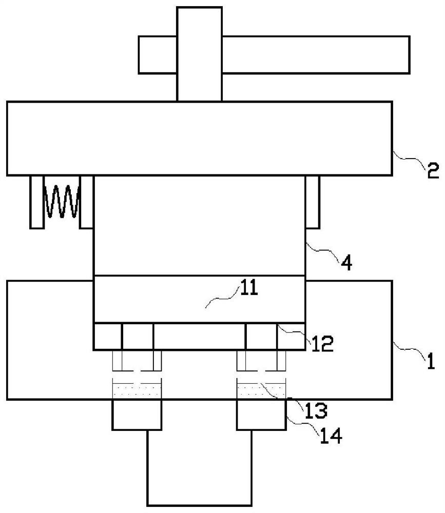
[0013] Below in conjunction with accompanying drawing and embodiment the present invention is further described:

[0014] Such as figure 1 , figure 2 , image 3 As shown in the embodiment, the anti-deformation automatic protection air pressure bench vise is a kind of automatic detection of the change of the clamping force on the workpiece when tightening through the adjustment of the air pressure, and automatically loosens to protect the workpiece when excessive tightening occurs. In addition, the device that shortens the clamping and correction time of the workpiece and improves the clamping efficiency includes a fixed jaw module 1; a turntable seat 10 is arranged at the bottom of the fixed jaw module 1, and A sliding hole is provided, and a nut is fixedly installed in the sliding hole, and a screw rod 3 is assembled in the nut; a movable jaw module 2 is arranged in front of the fixed jaw module 1, and the movable jaw module 2 includes screw rod 3 rocker, the screw rod 3 ...


PUM


Abstract

The invention provides an anti-deformation auto-protecting pneumatic bench vice. The anti-deformation auto-protecting pneumatic bench vice includes a fixed vice jaw module, and a sliding slot is formed in the side, directly facing a movable vice jaw module, of the fixed jaw module. The sliding slot is internally and slidably provided with a push plate, a piezoelectric material is disposed on the front end surface of the push plate, and a telescopic rod is vertically fixed to the rear end surface of the push plate. A telescopic hole is formed in the rear end surface of the sliding slot, a solenoid valve is disposed at the rear end of the telescopic hole in a sealed mode, and the solenoid valve is connected with the piezoelectric material through a wire. A piston is disposed at the rear endof the telescopic rod, and the piston is slidably disposed in the telescopic hole. According to the anti-deformation auto-protecting pneumatic bench vice, the change of the clamping force received bya workpiece during the tightening is automatically detected through the adjustment of the air pressure; and when excessive tightening occurs, the workpiece is automatically released to be protected, the clamping and correcting time of the workpiece is shortened, and the clamping efficiency is improved.

Description

technical field [0001] The invention relates to the field of clamps, in particular to a pneumatic clamp. Background technique [0002] Fixture refers to the device used to fix the processing object in the process of mechanical manufacturing so that it can occupy the correct position to accept construction or inspection, also known as fixture. Fixtures are usually composed of positioning elements, clamping devices, tool setting guide elements, indexing devices, connecting elements, and clamp bodies. When the existing fixture clamps the workpiece, it usually takes the two parallel surfaces of the workpiece as the reference plane, and then clamps it through the tightening device on the fixture; when the material of the workpiece is soft, the user must clamp it when clamping. Reasonably control the clamping force. If the clamping force is too small, it will cause the workpiece to be clamped loosely, and the workpiece will move during processing; if the clamping force is too lar...

Claims


Application Information

Patent Timeline
Patent Type & Authority Patents(China)
IPC IPC(8): B25B1/10B25B1/24
CPCB25B1/103B25B1/24
Inventor 吴成强
Owner 山东华源索具有限公司
Why Eureka
Try Eureka