
Automatic conveying device of ink machine

An automatic transmission and ink technology, applied in the general parts of printing machinery, printing machines, printing and other directions, can solve the problems of complex structure, troublesome disassembly and assembly, and large size of the ink machine.

Pending Publication Date: 2018-08-17
浙江寿原机械有限公司
View PDF9 Cites 0 Cited by
  • Summary
  • Abstract
  • Description
  • Claims
  • Application Information

AI Technical Summary

Problems solved by technology

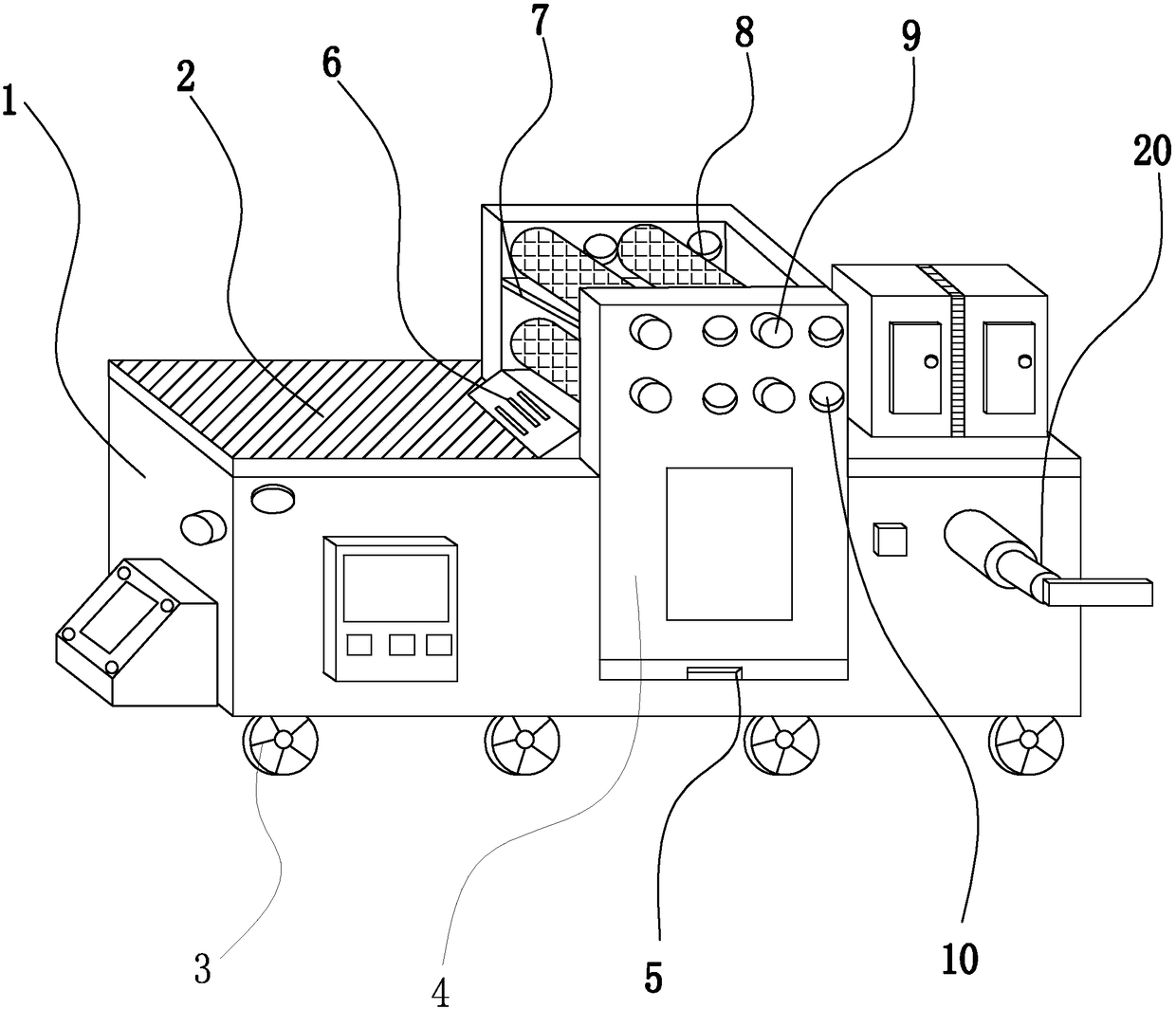
[0004] The purpose of the present invention is to provide an automatic conveying device for an ink machine to solve the problem in the above-mentioned background technology that when using an ink machine to transport an item to be printed, the dust on the surface of the item will fall on the ink machine as the ink machine is conveyed. Therefore, it is necessary to clean the inside of the ink machine in time so as not to cause blockage, but the ink machine is large in size and complex in structure, which makes disassembly and assembly very troublesome. At the same time, inks of different colors will splash and mix colors during printing, thus Problems that degrade print quality

Method used


Image

  • Automatic conveying device of ink machine
  • Automatic conveying device of ink machine
  • Automatic conveying device of ink machine

Examples


Embodiment Construction

[0017] The following will clearly and completely describe the technical solutions in the embodiments of the present invention with reference to the accompanying drawings in the embodiments of the present invention. Obviously, the described embodiments are only some, not all, embodiments of the present invention. Based on the embodiments of the present invention, all other embodiments obtained by persons of ordinary skill in the art without making creative efforts belong to the protection scope of the present invention.

[0018] In describing the present invention, it should be understood that the terms "upper", "lower", "front", "rear", "left", "right", "top", "bottom", "inner", " The orientation or positional relationship indicated by "outside", etc. is based on the orientation or positional relationship shown in the drawings, and is only for the convenience of describing the present invention and simplifying the description, rather than indicating or implying that the referre...


PUM


Abstract

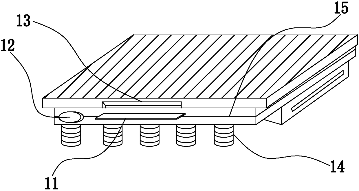
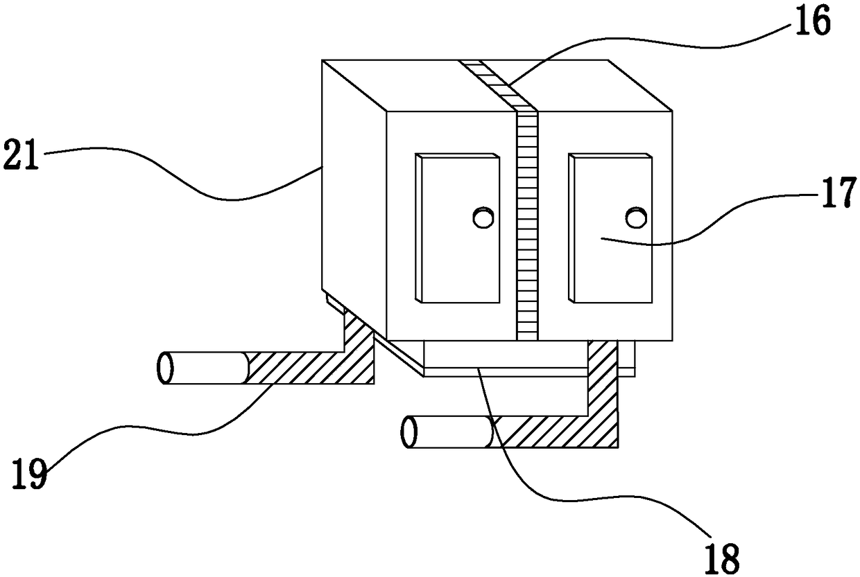
The invention relates to the technical field of ink machines, in particular to an automatic conveying device of an ink machine. The automatic conveying device comprises a device body, wherein idler wheels are fixedly connected to the two sides of the lower portion of the device body, a conveying plate is movably connected above the device body, a transverse groove is formed in the front opening ofthe conveying plate, a bottom plate is fixedly connected below the conveying plate, a button is fixedly connected in front of the bottom plate, and a transverse plate is arranged on the front side and the rear side of the bottom plate and located on the right side of the button. When the automatic conveying device of the ink machine is used for filling ink, a pushing plate is pushed away firstly,light-colored ink and dark-color ink are placed in an oil ink box and are separated through the plate, and when the ink sinks, the impurities in the ink are filtered into a bottom box, the ink is guided into a printing body through a discharging pipe, a rotary knob is rotated, an object to be printed is hung on shaft bodies, the shaft bodies are installed in holes, and then the shaft bodies are fixed through tightening the knob; and when printing is carried out, a partition plate separates the shaft bodies, so that ink splashing caused by too high rotating speed is avoided.

Description

technical field [0001] The invention relates to the technical field of ink machines, in particular to an automatic transmission device of an ink machine. Background technique [0002] Modern ink machines are generally composed of plate loading, ink application, embossing, paper feeding (including folding) and other mechanisms. Its working principle is: first make printing plates from the text and images to be printed, install them on the ink machine, and then manually Or the ink machine applies ink to the place where there are text and images on the printing plate, and then directly or indirectly transfers to paper or other substrates (such as textiles, metal plates, plastics, leather, wood, glass and ceramics), In order to reproduce the same printed matter as the printing plate, the invention and development of the ink machine played an important role in the spread of human civilization and culture. [0003] However, in the existing automatic transmission device of the ink...

Claims


Application Information

Patent Timeline
Patent Type & Authority Applications(China)
IPC IPC(8): B41F31/02
CPCB41F31/02
Inventor 纪平柯其方王健宋春磊徐伟
Owner 浙江寿原机械有限公司
Learn More