High comfort performance independent suspension for new energy bus

A technology of independent suspension and bus, which is applied in the direction of suspension, cantilever installed on the pivot, vehicle components, etc., which can solve the problem of large distance from the center of the brake disc to the mounting surface of the hub, which is not conducive to the life of the hub bearing, and increases the Wheel hub bearing load and other issues to achieve the effect of improving the lubrication environment, improving stability and comfort, and increasing the inclination angle

Pending Publication Date: 2018-08-17
方盛车桥(苏州)有限公司
View PDF8 Cites 7 Cited by
  • Summary
  • Abstract
  • Description
  • Claims
  • Application Information

AI Technical Summary

Problems solved by technology

After the gap is generated, the front wheel alignment parameters will change in real time, which will cause the body to bump and wear tires
Due to the limitation of the T-shaped joint structure and the structure of the solid kingpin, the distance from the center of the brake disc to the mounting surface of the wheel hub is large, and the distance between the center of the brake disc and the force center of the tire is large, which increases the braking deflection moment generated by vehicle braking, and is not It is conducive to the stability of the vehicle when braking, and at the same time increases the load on the hub bearing, which is not conducive to the life of the hub bearing

Method used


Image

  • High comfort performance independent suspension for new energy bus
  • High comfort performance independent suspension for new energy bus
  • High comfort performance independent suspension for new energy bus

Examples


Embodiment

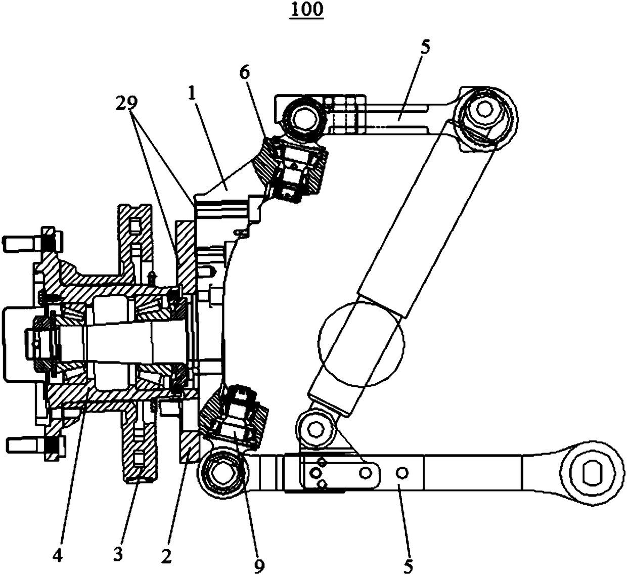
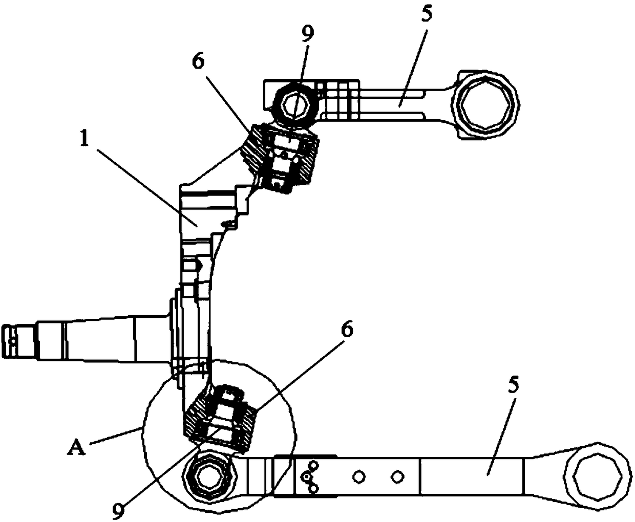
[0031] Please refer to Figure 1-Figure 6 , the present embodiment is a high-comfort independent suspension 100 for a new energy bus, which includes a steering knuckle assembly 1, a mounting plate 2 fixed on the end surface of the steering knuckle assembly 1, a brake disc 3, and a wheel hub assembly 4 And the control arm 5 connected with the steering knuckle assembly 1, the upper and lower ends of the steering knuckle assembly 1 are provided with connecting lugs 6, and the control arm 5 and the connecting lugs 6 are rotatably connected by a short pin rotary member.

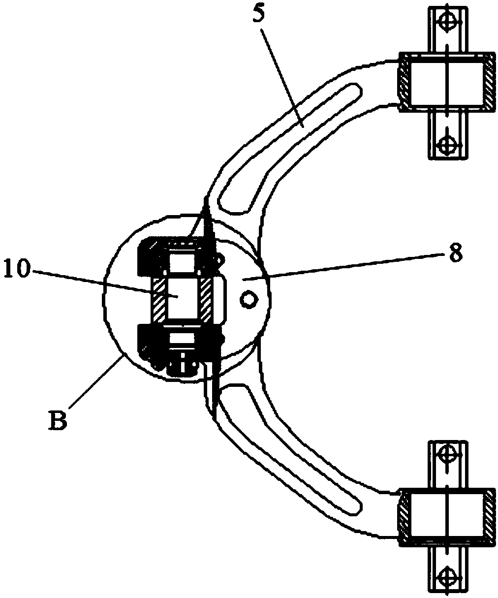
[0032] A stepped installation hole 7 is formed inside the connecting ear piece 6, a U-shaped fork 8 is provided at the end of the control arm 5, and coaxial installation holes (not marked in the figure) are arranged on both sides of the U-shaped fork 8. The pin rotary member includes a short pin connector 9 with one end connected to the mounting hole 7 bearings and a T-shaped joint 10 with both ends mounted in the...


PUM


Abstract

The invention discloses a high comfort performance independent suspension for a new energy bus. The high comfort performance independent suspension for the new energy bus comprises a steering knuckleassembly, a mounting plate, a brake disc, a hub assembly and a control arm, wherein the mounting plate, the brake disc and the hub assembly are fixed on the end surface of the steering knuckle assembly; the control arm is connected with the steering knuckle assembly; connecting lug blocks are arranged at the upper and lower ends of the steering knuckle assembly; the control arm is connected with the connecting lug block through a short pin rotating piece in a rotating manner; a step-shaped mounting hole is formed in the connecting lug block; a U-shaped fork is arranged at the end part of the control arm; coaxial mounting holes are formed in the two sides of the U-shaped fork; the short pin rotating piece comprises a short pin connecting piece and a T-shaped knuckle, wherein one end of theshort pin connecting piece is connected with the mounting hole through a bearing, and the two ends of the T-shaped knuckle are erected in the coaxial mounting holes through bearings; and the other endof the short pin connecting piece is fixedly connected with the T-shaped knuckle. According to the high comfort performance independent suspension for the new energy bus, the kingpin offset distanceis reduced, the kingpin inclination angle is increased, and the stability and comfort of the braking of the complete bus are improved.

Description

【Technical field】 [0001] The invention relates to a suspension structure, in particular to an independent suspension with high comfort for a new energy bus. 【Background technique】 [0002] Car suspension is an important part to ensure ride comfort. At the same time, the suspension of a bus, as a force transmission device connecting the frame (or body) and the axle (or wheel), is also an important part to ensure the safety of the bus, and it is one of the indicators to measure the comfort of the bus. Due to the fact that there are few independent suspension manufacturers before research and development for 7-9m buses, there are few suitable tonnage front independent suspension varieties available for selection, which cannot form a wide industrial effect and limit the promotion of corresponding independent suspensions. At present, the domestic small tonnage front independent suspension is mainly based on the solid kingpin structure. Due to the influence of the steering knuckl...

Claims


Application Information

Patent Timeline
Patent Type & Authority Applications(China)
IPC IPC(8): B62D7/18B60G7/00
CPCB62D7/18B60G7/008B60G2200/10
Inventor 曹崇禧杜冀林黄永亮曹鑫
Owner 方盛车桥(苏州)有限公司
Why Eureka
Try Eureka