

Sewing machine
A sewing machine and motor technology, applied in the field of sewing machines, can solve the problems of component loss, increased power consumption, damage, etc., and achieve the effect of reducing component loss and power consumption
- Summary
- Abstract
- Description
- Claims
- Application Information
AI Technical Summary
Problems solved by technology
Method used
Image

Examples
Embodiment Construction
[0071] [Outline of Embodiments of the Invention]
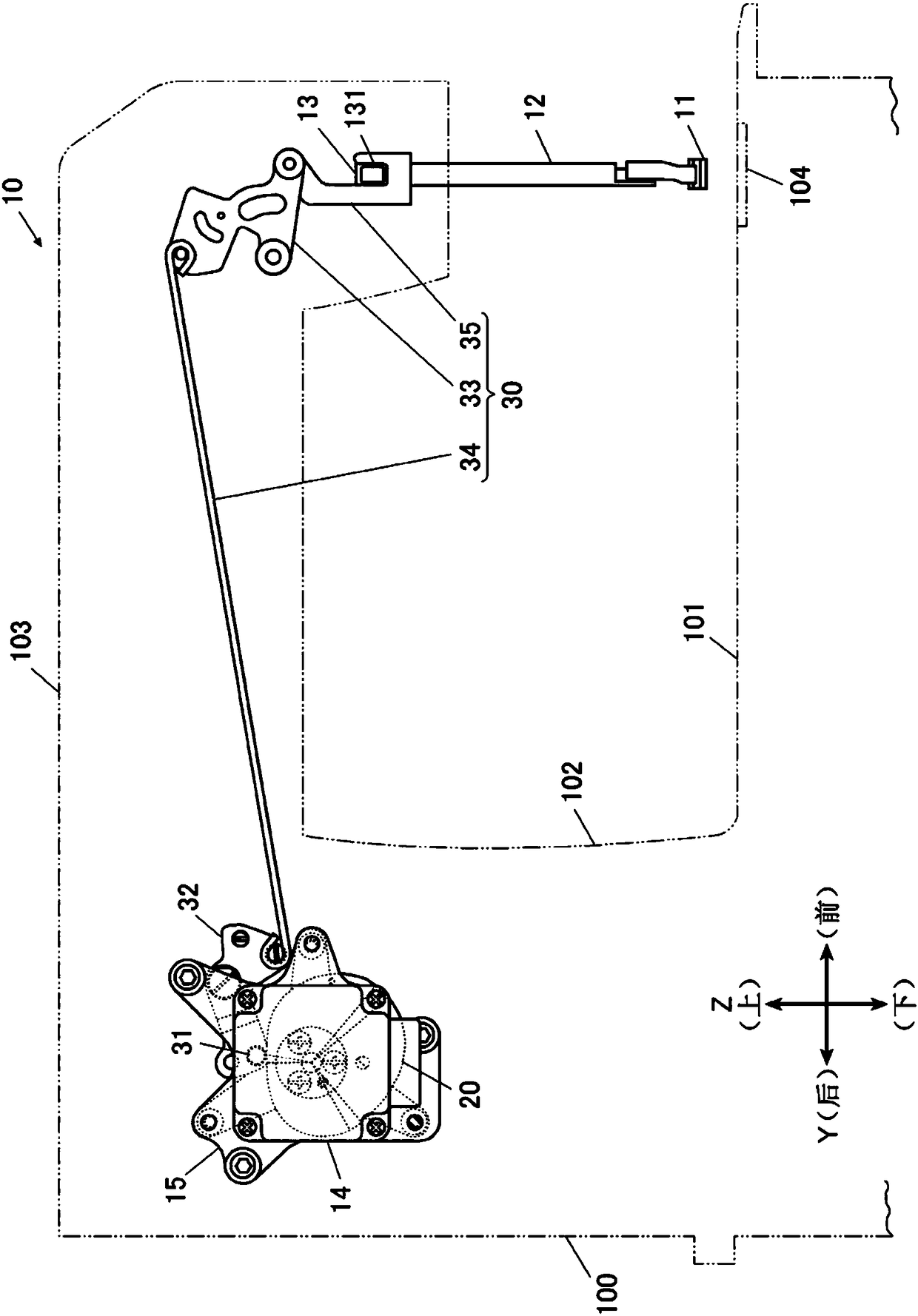
[0072] Next, a sewing machine according to the present invention will be described with reference to the drawings. figure 1 It is a side view showing the arrangement of the overall structure of a sewing machine frame 100 included in the sewing machine and a presser foot lifting mechanism 10 in the sewing machine frame 100 .
[0073]In addition, the sewing machine of this embodiment is a so-called lockstitch sewing machine, and the presser foot lifting mechanism 10 of the sewing machine which is a characteristic part of the present invention will be mainly described. Since the feeding mechanism, kettle mechanism, thread regulator device, balance mechanism, and thread cutting device have the same structure as known structures, description thereof will be omitted.
[0074] In addition, in the following description, the horizontal direction and along the figure 1 The longitudinal direction of the base portion 101 of the illustra...
PUM
 Abstract
Description
Claims
Application Information